- 您現(xiàn)在的位置:買賣IC網 > PDF目錄379094 > CY7C43644 (Cypress Semiconductor Corp.) 1K x36 x2 Bidirectional Synchronous FIFO w/ Bus Matching(1K x36 x2 雙向同步先進先出帶總線匹配) PDF資料下載
參數資料
| 型號: | CY7C43644 |
| 廠商: | Cypress Semiconductor Corp. |
| 英文描述: | 1K x36 x2 Bidirectional Synchronous FIFO w/ Bus Matching(1K x36 x2 雙向同步先進先出帶總線匹配) |
| 中文描述: | 每1000 x36 x2雙向同步FIFO瓦特/總線匹配(每1000 x36 x2雙向同步先進先出帶總線匹配) |
| 文件頁數: | 8/37頁 |
| 文件大?。?/td> | 581K |
| 代理商: | CY7C43644 |
第1頁第2頁第3頁第4頁第5頁第6頁第7頁當前第8頁第9頁第10頁第11頁第12頁第13頁第14頁第15頁第16頁第17頁第18頁第19頁第20頁第21頁第22頁第23頁第24頁第25頁第26頁第27頁第28頁第29頁第30頁第31頁第32頁第33頁第34頁第35頁第36頁第37頁
CY7C43624
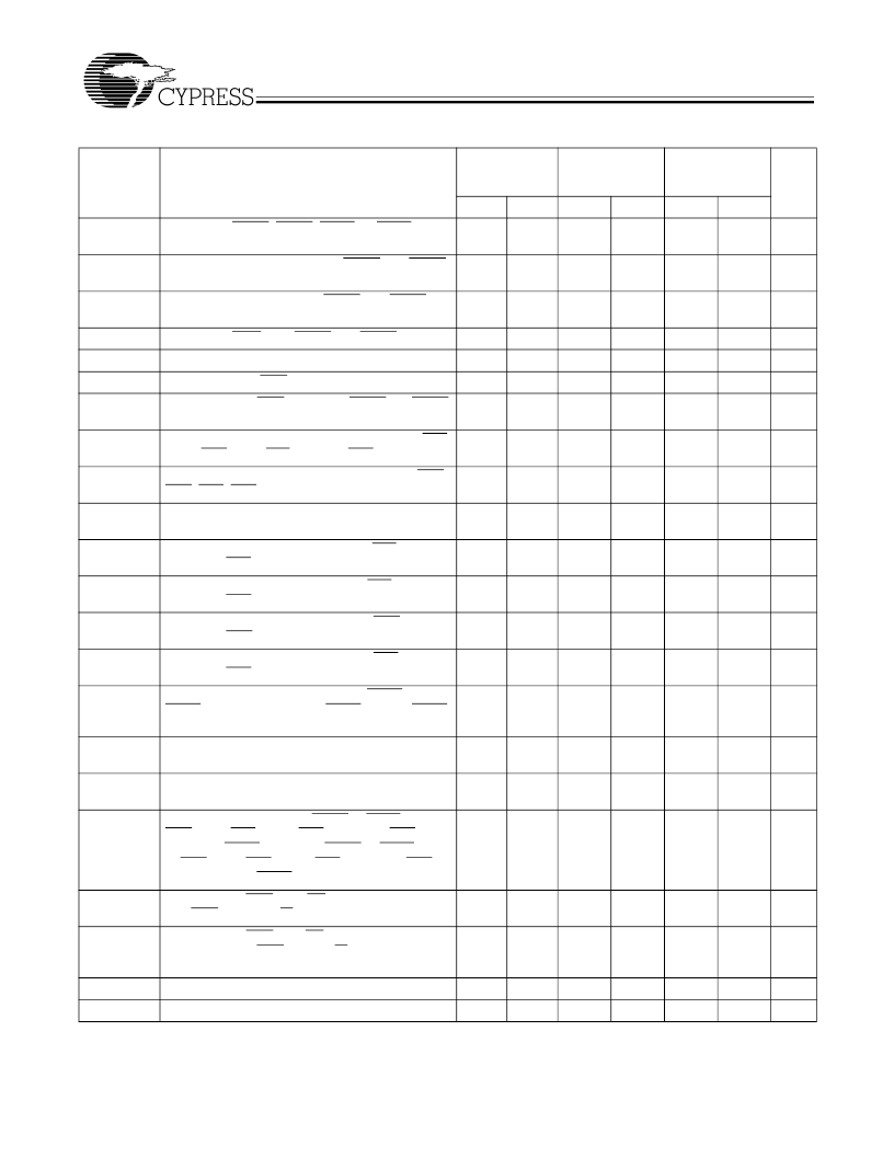
CY7C43634/CY7C43644
CY7C43664/CY7C43684
8
PRELIMINARY
t
RSTH
Hold Time, MRS1, MRS2, PRS1, or PRS2 LOW
after CLKA
↑
or CLKB
↑
[7]
Hold Time, FS0 and FS1 after MRS1 and MRS2
HIGH
1
2
4
ns
t
FSH
1
1
2
ns
t
BEH
Hold Time, BE/FWFT after MRS1 and MRS2
HIGH
1
1
2
ns
t
SPMH
t
SDH
t
SENH
t
SPH
Hold Time, SPM after MRS1 and MRS2 HIGH
Hold Time, FS0/SD after CLKA
↑
Hold Time, FS1/SEN after CLKA
↑
Hold Time, FS1/SEN HIGH after MRS1 and MRS2
HIGH
Skew Time between CLKA
↑
and CLKB
↑
for EFA/
ORA, EFB/ORB, FFA/IRA, and FFB/IRB
Skew Time between CLKA
↑
and CLKB
↑
for AEA,
AEB, AFA, AFB
Access Time, CLKA
↑
to A
0
–
35
and CLKB
↑
to
B
0
–
35
Propagation Delay Time, CLKA
↑
to FFA/IRA and
CLKB
↑
to FFB/IRB
Propagation Delay Time, CLKA
↑
to EFA/ORA and
CLKB
↑
to EFB/ORB
Propagation Delay Time, CLKA
↑
to AEA and
CLKB
↑
to AEB
Propagation Delay Time, CLKA
↑
to AFA and
CLKB
↑
to AFB
Propagation Delay Time, CLKA
↑
to MBF1 LOW or
MBF2 HIGH and CLKB
↑
to MBF2 LOW or MBF1
HIGH
Propagation Delay Time, CLKA
↑
to B
0
–
35[9]
and
CLKB
↑
to A
0
–
35[10]
Propagation Delay Time, MBA to A
0
–
35
Valid and
MBB to B
0
–
35
Valid
Propagation Delay Time, MRS1 or PRS1 LOW to
AEB LOW, AFA HIGH, FFA/IRA LOW, EFB/ORB
LOW and MBF1 HIGH and MRS2 or PRS2 LOW
to AEA LOW, AFB HIGH, FFB/IRB LOW, EFA/
ORA LOW and MBF2 HIGH
1
1
2
ns
0
0
0
ns
0
0
0
ns
0
1
2
ns
t
SKEW1[8]
5
5
7.5
ns
t
SKEW2[8]
7
8
12
ns
t
A
1
6
1
8
3
10
ns
t
WFF
1
6
1
8
2
8
ns
t
REF
1
6
1
8
1
8
ns
t
PAE
1
6
1
8
1
8
ns
t
PAF
1
6
1
8
1
8
ns
t
PMF
0
6
0
8
0
12
ns
t
PMR
1
7
2
11
3
12
ns
t
MDV
1
6
2
9
3
11
ns
t
RSF
1
6
1
10
1
15
ns
t
EN
Enable Time, CSA or W/RA LOW to A
0
–
35
Active
and CSB LOW and W/RB HIGH to B
0
–
35
Active
Disable Time, CSA or W/RA HIGH to A
0
–
35
at High
Impedance and CSB HIGH or W/RB LOW to B
0
–
35
at High Impedance
1
5
2
8
2
10
ns
t
DIS
1
5
1
6
1
8
ns
t
PRT
t
RTR
Notes:
8.
Retransmit Pulse Width
60
60
60
ns
Retransmit recovery Time
90
90
90
ns
Skew time is not a timing constraint for proper device operation and is only included to illustrate the timing relationship between the CLKA cycle and the CLKB
cycle.
Writing data to the Mail1 register when the B
0
–
35
outputs are active and MBB is HIGH.
10. Writing data to the Mail2 register when the A
0
–
35
outputs are active and MBA is HIGH.
9.
Switching Characteristics
Over the Operating Range (continued)
Parameter
Description
CY7C43624/
34/44/64/84
–
7
CY7C43624/
34/44/64/84
–
10
CY7C43624/
34/44/64/84
–
15
Unit
Min.
Max.
Min.
Max.
Min.
Max.
相關PDF資料 |
PDF描述 |
|---|---|
| CY7C43664 | 4K x36 x2 Bidirectional Synchronous FIFO w/ Bus Matching(4K x36 x2 雙向同步先進先出帶總線匹配) |
| CY7C43684 | 16K x36 x2 Bidirectional Synchronous FIFO w/ Bus Matching(16K x36 x2 雙向同步先進先出帶總線匹配) |
| CY7C43636 | 512 x36/x18x2 Tri Bus FIFO(512 x36/x18x2 三路總線 先進先出) |
| CY7C43626 | 256 x36/x18x2 Tri Bus FIFO(256 x36/x18x2 三路總線先進先出) |
| CY7C43646 | 1K x36/x18x2 Tri Bus FIFO(1K x36/x18x2 三路總線 先進先出) |
相關代理商/技術參數 |
參數描述 |
|---|---|
| CY7C43644AV-10AC | 制造商:Cypress Semiconductor 功能描述:FIFO Mem Sync Dual Depth/Width Bi-Dir 1K x 36 x 2 128-Pin TQFP |
| CY7C43663-15AC | 制造商:Rochester Electronics LLC 功能描述:- Bulk |
| CY7C43664-7AC | 制造商:Rochester Electronics LLC 功能描述:- Bulk |
| CY7C43682-15AC | 制造商:Rochester Electronics LLC 功能描述:- Bulk |
| CY7C43683-10AI | 制造商:Rochester Electronics LLC 功能描述:- Bulk |
發(fā)布緊急采購,3分鐘左右您將得到回復。