- 您現(xiàn)在的位置:買賣IC網(wǎng) > PDF目錄379097 > CY8C24794-SPC (Cypress Semiconductor Corp.) PSoCTM Mixed-Signal Array PDF資料下載
參數(shù)資料
| 型號: | CY8C24794-SPC |
| 廠商: | Cypress Semiconductor Corp. |
| 英文描述: | PSoCTM Mixed-Signal Array |
| 中文描述: | PSoCTM混合信號陣列 |
| 文件頁數(shù): | 28/32頁 |
| 文件大?。?/td> | 366K |
| 代理商: | CY8C24794-SPC |
第1頁第2頁第3頁第4頁第5頁第6頁第7頁第8頁第9頁第10頁第11頁第12頁第13頁第14頁第15頁第16頁第17頁第18頁第19頁第20頁第21頁第22頁第23頁第24頁第25頁第26頁第27頁當(dāng)前第28頁第29頁第30頁第31頁第32頁
April 14, 2005
Document No. 38-12018 Rev. *F
28
CY8C24794 Final Data Sheet
3. Electrical Specifications
3.4.9
AC I
2
C Specifications
The following table lists guaranteed maximum and minimum specifications for the voltage and temperature ranges: 4.75V to 5.25V
and -40
°
C
≤
T
A
≤
85
°
C, or 3.0V to 3.6V and -40
°
C
≤
T
A
≤
85
°
C, respectively. Typical parameters apply to 5V and 3.3V at 25
°
C and
are for design guidance only.
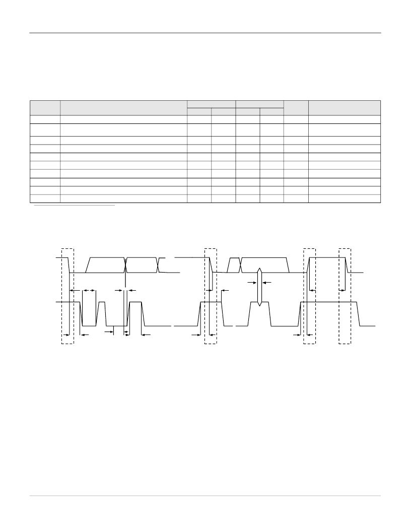
Figure 3-6. Definition for Timing for Fast/Standard Mode on the I
2
C Bus
Table 3-26. AC Characteristics of the I
2
C SDA and SCL Pins for Vdd
Symbol
F
SCLI2C
T
HDSTAI2C
Description
Standard Mode
Min
Fast Mode
Min
Units
kHz
Notes
Max
Max
SCL Clock Frequency
0
100
0
400
Hold Time (repeated) START Condition. After this period,
the first clock pulse is generated.
LOW Period of the SCL Clock
4.0
–
0.6
–
μ
s
T
LOWI2C
T
HIGHI2C
T
SUSTAI2C
T
HDDATI2C
T
SUDATI2C
T
SUSTOI2C
T
BUFI2C
T
SPI2C
4.7
–
1.3
–
μ
s
μ
s
μ
s
μ
s
ns
HIGH Period of the SCL Clock
4.0
–
0.6
–
Set-up Time for a Repeated START Condition
4.7
–
0.6
–
Data Hold Time
0
–
0
–
Data Set-up Time
250
–
100
a
0.6
a. A Fast-Mode I2C-bus device can be used in a Standard-Mode I2C-bus system but the requirement t
SU;DAT
≥
250 ns must then be met. This will automatically be the case if
the device does not stretch the LOW period of the SCL signal. If such device does stretch the LOW period of the SCL signal, it must output the next data bit to the SDA line
t
rmax
+ t
SU;DAT
= 1000 + 250 = 1250 ns (according to the Standard-Mode I2C-bus specification) before the SCL line is released.
–
Set-up Time for STOP Condition
4.0
–
–
μ
s
μ
s
ns
Bus Free Time Between a STOP and START Condition
4.7
–
1.3
–
Pulse Width of spikes are suppressed by the input filter.
–
–
0
50
SDA
SCL
S
Sr
S
P
T
BUFI2C
T
SPI2C
T
HDSTAI2C
T
SUSTOI2C
T
SUSTAI2C
T
LOWI2C
T
HIGHI2C
T
HDDATI2C
T
HDSTAI2C
T
SUDATI2C
相關(guān)PDF資料 |
PDF描述 |
|---|---|
| CY8C24794-SPSX | PSoCTM Mixed-Signal Array |
| CY8C27543-24AXI | PSoC Mixed Signal Array |
| CY8C27643-24LFI | PSoC Mixed Signal Array |
| CY8C27643-24LFIT | PSoC Mixed Signal Array |
| CY8C27643-24LFXI | PSoC Mixed Signal Array |
相關(guān)代理商/技術(shù)參數(shù) |
參數(shù)描述 |
|---|---|
| CY8C24794-SPE | 制造商:CYPRESS 制造商全稱:Cypress Semiconductor 功能描述:PSoCTM Mixed-Signal Array |
| CY8C24794-SPI | 制造商:CYPRESS 制造商全稱:Cypress Semiconductor 功能描述:PSoCTM Mixed-Signal Array |
| CY8C24794-SPLFX | 制造商:CYPRESS 制造商全稱:Cypress Semiconductor 功能描述:PSoCTM Mixed-Signal Array |
| CY8C24794-SPPVX | 制造商:CYPRESS 制造商全稱:Cypress Semiconductor 功能描述:PSoCTM Mixed-Signal Array |
| CY8C24794-SPPX | 制造商:CYPRESS 制造商全稱:Cypress Semiconductor 功能描述:PSoCTM Mixed-Signal Array |
發(fā)布緊急采購,3分鐘左右您將得到回復(fù)。