- 您現(xiàn)在的位置:買賣IC網(wǎng) > PDF目錄379184 > DS87C520-WCL EPROM/ROM High-Speed Micro PDF資料下載
參數(shù)資料
| 型號(hào): | DS87C520-WCL |
| 英文描述: | EPROM/ROM High-Speed Micro |
| 中文描述: | 存儲(chǔ)器/ ROM的高速微 |
| 文件頁(yè)數(shù): | 26/45頁(yè) |
| 文件大?。?/td> | 1415K |
| 代理商: | DS87C520-WCL |
第1頁(yè)第2頁(yè)第3頁(yè)第4頁(yè)第5頁(yè)第6頁(yè)第7頁(yè)第8頁(yè)第9頁(yè)第10頁(yè)第11頁(yè)第12頁(yè)第13頁(yè)第14頁(yè)第15頁(yè)第16頁(yè)第17頁(yè)第18頁(yè)第19頁(yè)第20頁(yè)第21頁(yè)第22頁(yè)第23頁(yè)第24頁(yè)第25頁(yè)當(dāng)前第26頁(yè)第27頁(yè)第28頁(yè)第29頁(yè)第30頁(yè)第31頁(yè)第32頁(yè)第33頁(yè)第34頁(yè)第35頁(yè)第36頁(yè)第37頁(yè)第38頁(yè)第39頁(yè)第40頁(yè)第41頁(yè)第42頁(yè)第43頁(yè)第44頁(yè)第45頁(yè)
DS87C520/DS83C520 EPROM/ROM High-Speed Microcontrollers
26 of 45
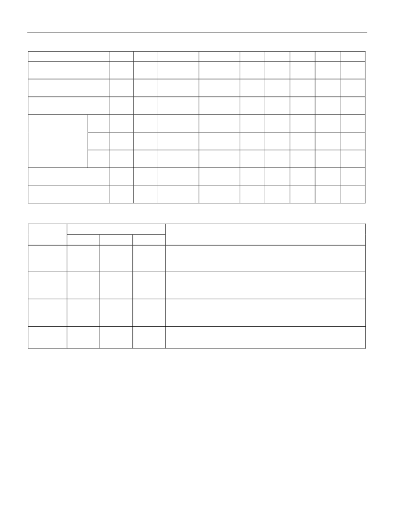
Table 9. EPROM Programming Modes
MODE
RST
PSEN
ALE/
PROG
EA
/VPP
P2.6
P2.7
P3.3
P3.6
P3.7
Program Code Data
H
L
PL
12.75V
L
H
H
H
H
Verify Code Data
H
L
H
H
L
L
L
H
H
Program Encryption Array
Address 0-3Fh
H
L
PL
12.75V
L
H
H
L
H
LB1
H
L
PL
12.75V
H
H
H
H
H
LB2
H
L
PL
12.75V
H
H
H
L
L
Program Lock Bits
LB3
H
L
PL
12.75V
H
L
H
H
L
Program Option Register
Address FCh
Read Signature or Option
Registers 30, 31, 60 FCh
H
L
PL
12.75V
L
H
H
L
L
H
L
H
H
L
L
L
L
L
Table 10. DS87C520 EPROM Lock Bits
LOCK BITS
LEVEL
LB1
LB2
LB3
PROTECTION
1
U
U
U
No program lock. Encrypted verify if encryption table was
programmed.
2
P
U
U
Prevent MOVC instructions in external memory from reading
program bytes in internal memory.
EA
is sampled and latched on
reset. Allow no further programming of EPROM.
Level 2 plus no verify operation. Also, prevent MOVX
instructions in external memory from reading SRAM (MOVX) in
internal memory.
3
P
P
U
4
P
P
P
Level 3 plus no external execution.
SECURITY OPTIONS
The DS87C520 employs a standard three-level lock that restricts viewing of the EPROM contents. A 64-
byte Encryption Array allows the authorized user to verify memory by presenting the data in encrypted
form.
Lock Bits
The security lock consists of three lock bits. These bits select a total of four levels of security. Higher
levels provide increasing security but also limit application flexibility. Table 10 shows the security
settings. Note that the programmer cannot directly read the state of the security lock. User software has
access to this information as described in the
Memory
section.
相關(guān)PDF資料 |
PDF描述 |
|---|---|
| DS87C520MCL | EPROM/ROM High-Speed Microcontrollers |
| DS9034PC | PowerCap |
| DS9034PCI | PowerCap |
| DS9034PCX | RAMified Watchdog Timekeeper |
| DS9490B | USB to 1-Wire/iButton Adapter |
相關(guān)代理商/技術(shù)參數(shù) |
參數(shù)描述 |
|---|---|
| DS87C530 | 制造商:DALLAS 制造商全稱:Dallas Semiconductor 功能描述:EPROM MICRO WITH REAL TIME CLOCK |
| DS87C530_05 | 制造商:DALLAS 制造商全稱:Dallas Semiconductor 功能描述:EPROM/ROM Microcontrollers with Real-Time Clock |
| DS87C530_1 | 制造商:DALLAS 制造商全稱:Dallas Semiconductor 功能描述:EPROM/ROM Micro with Real Time Clock |
| DS87C530+ECL | 制造商:Maxim Integrated Products 功能描述:MICRO OTP RTC 33MHZ 52P TQFP PB-FRR - Trays |
發(fā)布緊急采購(gòu),3分鐘左右您將得到回復(fù)。