- 您現(xiàn)在的位置:買賣IC網(wǎng) > PDF目錄353106 > EL2082 (Intersil Corporation) Current Mode Multiplier PDF資料下載
參數(shù)資料
| 型號(hào): | EL2082 |
| 廠商: | Intersil Corporation |
| 英文描述: | Current Mode Multiplier |
| 中文描述: | 電流模式乘數(shù) |
| 文件頁數(shù): | 15/16頁 |
| 文件大小: | 357K |
| 代理商: | EL2082 |
EL2082C
Current-Mode Multiplier
Applications Information
Contd
The output current could be terminated witha1k
X load resistor to achieve a nominal voltage gain of 1
at the EL2082 but the IOUT load and stray capacitances would limit bandwidth greatly The lowest
practical total capacitance at IOUT is about 12 pF and this gives a 13 MHz bandwidth witha1kX
load In the above example a 100
X load is used for an upper limit of 130 MHz The operational
amplifier gives a gain of a10 to bring the overall gain to unity Wider bandwidth yet can be had by
installing CIN This is a very small capacitor typically 1 pf–2 pF and it bolsters the gain above
100 MHz Here is a table of results for this circuit used with various amplifiers
Operational
Power
b
3 dB
01 dB
Amplifier
Supplies
Rf
Rg
CIN
Bandwidth
Peaking
EL2020
g
5V
620
68
34 MHz
56 MHz
0
EL2020
g
15V
620
68
40 MHz
74 MHz
0
EL2130
g
5V
620
68
73 MHz
11 MHz
10 dB
EL2030
g
15V
620
68
93 MHz
12 MHz
13 dB
EL2090
g
15V
240
27
60 MHz
10 MHz
05 dB
EL2120
g
5V
220
24
57 MHz
10 MHz
04 dB
EL2120
g
15V
220
24
65 MHz
11 MHz
03 dB
EL2070
g
5V
200
22
2 pF
150 MHz
30 MHz
04 dB
EL2071
g
5V
15K
240
2 pF
200 MHz
30 MHz
0
EL2075
g
5V
620
68
2 pF
270 MHz
30 MHz
15 dB
Maximum bandwidth is maintained over a gain range of a6to b16 dB bandwidth drops at lower
gains If wider gain range with full bandwidth is required two or more EL2082’s can be cascaded with
the IOUT of one directly driving the IIN of the next
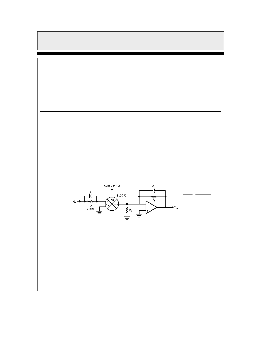
The EL2082 can also be used with an I
xV operational circuit
Gain eb
VGAIN
1V
RF
RIN a95X
J
2082 – 14
Inverting
EL2082 a Op-Amp
The circuit above gives a negative gain The main concern of this connection involves the total IOUT
and stray capacitances at the amplifier’s input When using traditional op-amps the pole caused by
these capacitances can make the amplifier less stable and even cause oscillations in amplifiers whose
gain-bandwidth is greater than 5 MHz A typical cure is to add a capacitor Cf in the 2 pF – 10 pF range
This will reduce overall bandwidth so a capacitor CIN can be added to regain frequency response The
ratio CfCIN is made equal to RIN Rf
8
相關(guān)PDF資料 |
PDF描述 |
|---|---|
| EL2160CS-T13 | 180MHz Current Feedback Amplifier |
| EL2160CS-T7 | 180MHz Current Feedback Amplifier |
| EL2244CM | Dual/Quad Low-Power 120MHz Unity-Gain Stable Op Amp |
| EL2244CM-T13 | Dual/Quad Low-Power 120MHz Unity-Gain Stable Op Amp |
| EL2244CMZ | Dual/Quad Low-Power 120MHz Unity-Gain Stable Op Amp |
相關(guān)代理商/技術(shù)參數(shù) |
參數(shù)描述 |
|---|---|
| EL2082C | 制造商:ELANTEC 制造商全稱:ELANTEC 功能描述:Current-Mode Multiplier |
| EL2082CJ | 制造商:未知廠家 制造商全稱:未知廠家 功能描述:Analog Multiplier |
| EL2082CN | 制造商:INTERSIL 制造商全稱:Intersil Corporation 功能描述:Current Mode Multiplier |
| EL2082CS | 制造商:INTERSIL 制造商全稱:Intersil Corporation 功能描述:Current Mode Multiplier |
| EL2082J | 制造商:未知廠家 制造商全稱:未知廠家 功能描述:Analog Multiplier |
發(fā)布緊急采購(gòu),3分鐘左右您將得到回復(fù)。