- 您現(xiàn)在的位置:買賣IC網(wǎng) > PDF目錄353104 > EL2252CN (INTERSIL CORP) TRANS ARRAY NPN/NPN SMINI-5 PDF資料下載
參數(shù)資料
| 型號: | EL2252CN |
| 廠商: | INTERSIL CORP |
| 元件分類: | 比較器 |
| 英文描述: | TRANS ARRAY NPN/NPN SMINI-5 |
| 中文描述: | DUAL COMPARATOR, 13000 uV OFFSET-MAX, PDIP14 |
| 封裝: | PLASTIC, DIP-14 |
| 文件頁數(shù): | 1/12頁 |
| 文件大小: | 300K |
| 代理商: | EL2252CN |
EL2252C
December
1995
Rev
E
EL2252C
Dual 50 MHz ComparatorPin Receiver
Note All information contained in this data sheet has been carefully checked and is believed to be accurate as of the date of publication however this data sheet cannot be a ‘‘controlled document’’ Current revisions if any to these
specifications are maintained at the factory and are available upon your request We recommend checking the revision level before finalization of your design documentation Patent pending
1995 Elantec Inc
Features
Fast response7 ns
Inputs tolerate large overdrives
with no speed nor bias current
penalties
Propagation delay is relatively
constant with variations of input
Slew Rate overdrive
temperature and supply voltage
Output provides proper CMOS or
TTL logic levels
Hysteresis is available on-chip
Large voltage gain8000 VV
Not oscillation-prone
Can detect 4 ns glitches
MIL-STD-883 Rev C compliant
Applications
Pin receiver for automatic test
equipment
Data communications line
receiver
Frequency counter input
Pulse squarer
Ordering Information
Part No
Temp Range
Package
Outline
EL2252CN
0 Cto a75 C
14-Pin P-DIP
MDP0031
EL2252CM
0 Cto a75 C
20-Lead SOL
MDP0027
General Description
The EL2252 dual comparator replaces the traditional input
buffer a attenuator aECL comparator aECL to TTL transla-
tor circuit blocks used in digital equipment The EL2252 pro-
vides a quick 7 ns propagation delay while complying with
g
10V inputs Input accuracy and propagation delay is main-
tained even with input signal Slew Rates as great as 4000 V
ms
The EL2252 can run on supplies as low as b52V and a9V and
comply with ECL and CMOS inputs or use supplies as great as
g
18V for much greater input range
The EL2252 has a
TTL pin which when grounded restricts
the output VOH to a TTL swing to minimize propagation delay
When left open the output VOH increases to a valid CMOS
level
The comparators are well behaved and have little tendency to
oscillate over a variety of input and output source and load
impedances They do not oscillate even when the inputs are
held in the linear range of the device To improve output stabili-
ty in the presence of input noise an internal 60 mV of hystere-
sis is available by connecting the HYS pin to Vb
Elantec’s products and facilities comply with MIL-I-45208A
and other applicable quality specifications For information on
Elantec’s processing see Elantec document QRA-1 ‘‘Elantec’s
Processing Monolithic Integrated Circuits
’’
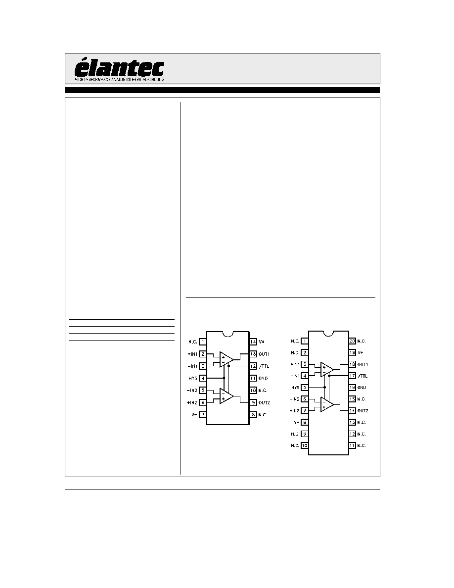
Connection Diagrams
14-Pin DIP
20-Pin SOL
2252 – 1
Top View
2252 – 2
Top View
相關(guān)PDF資料 |
PDF描述 |
|---|---|
| EL7252CS-T7 | Dual Input, High Speed, Dual Channel Power MOSFET Driver |
| EL5227CLZ | 2.5MHz 4, 8, 10 & 12 Channel Rail-to-Rail Buffers |
| EL5327CLZ | 2.5MHz 4, 8, 10 & 12 Channel Rail-to-Rail Buffers |
| EL2460CN | Dual/Quad 130MHz Current Feedback Amplifiers |
| EL2460CS | Dual/Quad 130MHz Current Feedback Amplifiers |
相關(guān)代理商/技術(shù)參數(shù) |
參數(shù)描述 |
|---|---|
| EL2252D | 制造商:未知廠家 制造商全稱:未知廠家 功能描述:Analog Comparator |
| EL2252J | 制造商:未知廠家 制造商全稱:未知廠家 功能描述:Analog Comparator |
| EL2252J/883B | 制造商:未知廠家 制造商全稱:未知廠家 功能描述:Analog Comparator |
| EL2256 | 制造商:Rittal 功能描述:ENCLOSURE COMBINATION 6U 制造商:Rittal 功能描述:ENCLOSURE, COMBINATION, 6U |
| EL2256 | 制造商:Rittal 功能描述:COMBINATION ENCLOSURE 6U |
發(fā)布緊急采購,3分鐘左右您將得到回復(fù)。