- 您現(xiàn)在的位置:買賣IC網(wǎng) > PDF目錄362761 > ER1006F (Won-Top Electronics Co., Ltd.) 10A ISOLATION SUPER-FAST GLASS PASSIVATED RECTIFIER PDF資料下載
參數(shù)資料
| 型號(hào): | ER1006F |
| 廠商: | Won-Top Electronics Co., Ltd. |
| 英文描述: | 10A ISOLATION SUPER-FAST GLASS PASSIVATED RECTIFIER |
| 中文描述: | 10A條分離超快速玻璃鈍化整流 |
| 文件頁數(shù): | 1/3頁 |
| 文件大小: | 48K |
| 代理商: | ER1006F |
ER1000F – ER1006F
1 of 3 2002 Won-Top Electronics
ER1000F – ER1006F
10A ISOLATION SUPER-FAST GLASS PASSIVATED RECTIFIER
Features
!
Glass Passivated Die Construction B
!
Super-Fast Switching for High Efficiency
!
High Current Capability C
!
Low Reverse Leakage Current
!
High Surge Current Capability G A
!
Plastic Material has UL Flammability
Classification 94V-O
PIN1 2
D
Mechanical Data
F
E
!
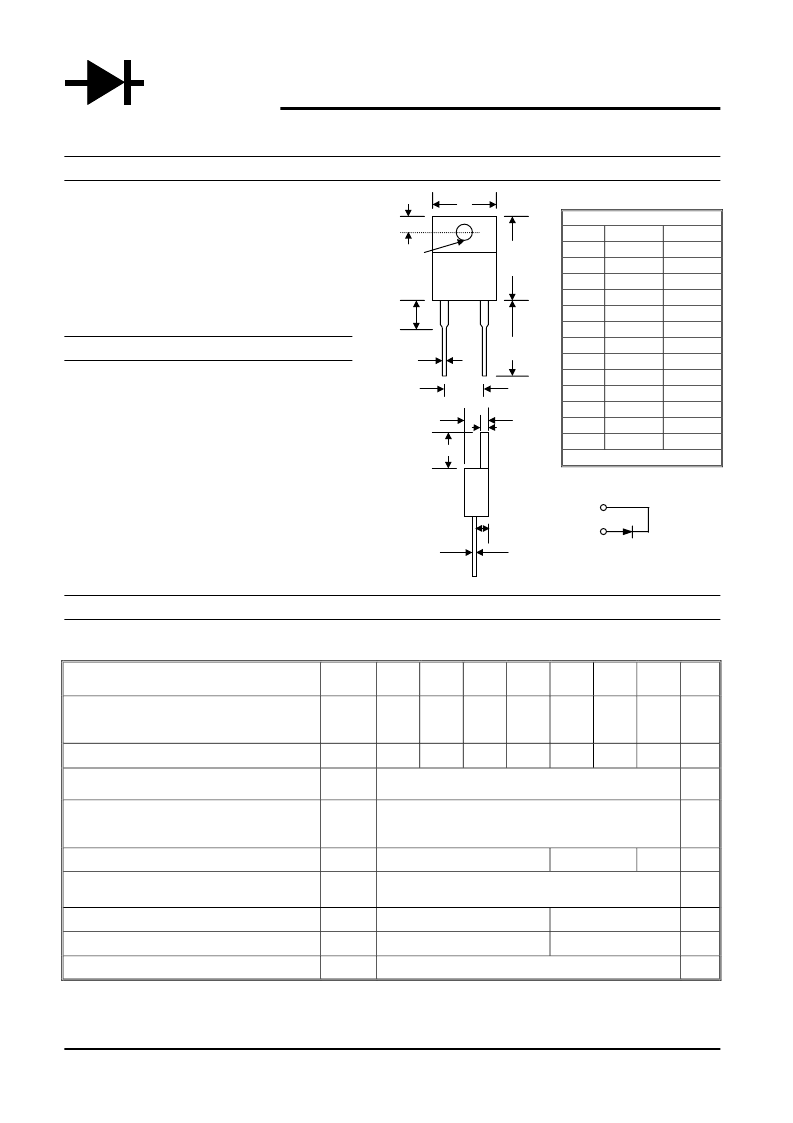
Case: ITO-220A Full Molded Plastic
!
Terminals: Plated Leads Solderable per P
MIL-STD-202, Method 208
!
Polarity: See Diagram I
!
Weight: 2.24 grams (approx.) L
!
Mounting Position: Any H
!
Marking: Type Number
PIN 1+
J
PIN 2 -
K
Maximum Ratings and Electrical Characteristics
@T
A
=25°C unless otherwise specified
Single Phase, half wave, 60Hz, resistive or inductive load.
For capacitive load, derate current by 20%.
Characteristic
Symbol
ER
1000F
ER
1001F
ER
1001AF
ER
1002F
ER
1003F
ER
1004F
ER
1006F
Unit
Peak Repetitive Reverse Voltage
Working Peak Reverse Voltage
DC Blocking Voltage
V
RRM
V
RWM
V
R
50
100
150
200
300
400
600
V
RMS Reverse Voltage
V
R(RMS)
35
70
105
140
210
280
420
V
Average Rectified Output Current @T
C
= 105°C
I
O
10
A
Non-Repetitive Peak Forward Surge Current 8.3ms
Single half sine-wave superimposed on rated load
(JEDEC Method)
I
FSM
150
A
Forward Voltage @I
F
= 10A
V
FM
0.95
1.3
1.7
V
Peak Reverse Current @T
A
= 25°C
At Rated DC Blocking Voltage @T
A
= 100°C
I
RM
10
500
μA
Reverse Recovery Time (Note 1)
t
rr
35
50
nS
Typical Junction Capacitance (Note 2)
C
j
70
50
pF
Operating and Storage Temperature Range
T
j
, T
STG
-65 to +150
°C
Note: 1. Measured with IF = 0.5A, IR = 1.0A, IRR = 0.25A.
2. Measured at 1.0 MHz and applied reverse voltage of 4.0V D.C.
WTE
POWER SEMICONDUCTORS
ITO-220A
Min
14.9
—
2.62
3.56
13.46
0.68
3.74
5.84
4.44
2.54
0.35
1.14
4.95
Dim
A
B
C
D
E
F
G
H
I
J
K
L
P
Max
15.1
10.5
2.87
4.06
14.22
0.94
3.91
6.86
4.70
2.79
0.64
1.40
5.20
All Dimensions in mm
相關(guān)PDF資料 |
PDF描述 |
|---|---|
| ER1006 | 10A SUPER-FAST GLASS PASSIVATED RECTIFIER |
| ER1006CT | 10A SUPER-FAST GLASS PASSIVATED RECTIFIER |
| ER1006FCT | 10A ISOLATION SUPER-FAST GLASS PASSIVATED RECTIFIER |
| ER100S | SUPERFAST RECOVERY RECTIFIERS |
| ER102S | SUPERFAST RECOVERY RECTIFIERS |
相關(guān)代理商/技術(shù)參數(shù) |
參數(shù)描述 |
|---|---|
| ER1006F _T0 _10001 | 制造商:PanJit Touch Screens 功能描述: |
| ER1006F_B0_10001#DELETED BY PJT# | 制造商:PanJit Touch Screens 功能描述: |
| ER1006F_T0_10001 | 制造商:PanJit Touch Screens 功能描述: |
| ER1006FCT | 制造商:WTE 制造商全稱:Won-Top Electronics 功能描述:10A ISOLATION SUPER-FAST GLASS PASSIVATED RECTIFIER |
| ER1006FCT _T0 _10001 | 制造商:PanJit Touch Screens 功能描述: |
發(fā)布緊急采購,3分鐘左右您將得到回復(fù)。