- 您現(xiàn)在的位置:買賣IC網(wǎng) > PDF目錄79143 > FS1001-9EPD9TB1 (POWER-ONE INC) 1-OUTPUT DC-DC REG PWR SUPPLY MODULE PDF資料下載
參數(shù)資料
| 型號: | FS1001-9EPD9TB1 |
| 廠商: | POWER-ONE INC |
| 元件分類: | 電源模塊 |
| 英文描述: | 1-OUTPUT DC-DC REG PWR SUPPLY MODULE |
| 封裝: | METAL, CASE S02, MODULE |
| 文件頁數(shù): | 11/33頁 |
| 文件大?。?/td> | 438K |
| 代理商: | FS1001-9EPD9TB1 |
第1頁第2頁第3頁第4頁第5頁第6頁第7頁第8頁第9頁第10頁當前第11頁第12頁第13頁第14頁第15頁第16頁第17頁第18頁第19頁第20頁第21頁第22頁第23頁第24頁第25頁第26頁第27頁第28頁第29頁第30頁第31頁第32頁第33頁
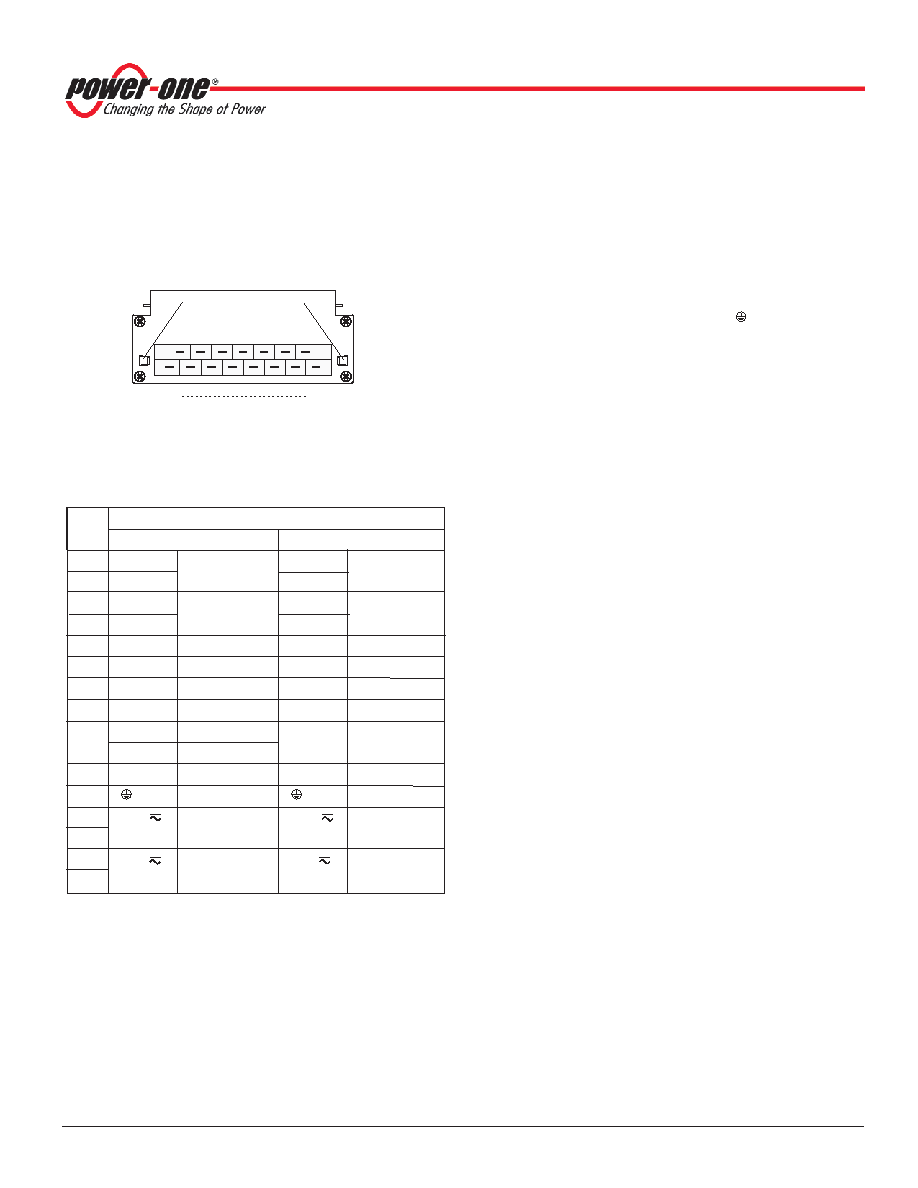
Table 12: H15 connector pin allocation
Pin
Connector type H15
No.
AS to LS1000
AS to LS2000
4
Vo1+
Pos. output 1
Vo2+
Pos. output 2
6
Vo1+
Vo2+
8
Vo1–
Neg. output 1
Vo2–
Neg. output 2
10
Vo1–
Vo2–
12
S+
Sense
Vo1+
Pos. output 1
14
S–
Sense
Vo1–
Neg. output 1
16
R
1
Control of
Vo
R
1
Control of
Vo1
18
i
Inhibit
i
Inhibit
20
D
3
Save data
D
3
Safe data
V
3
ACFAIL
22
T
5
Current share
T
5
Current share
24
2
Protective earth
26
Vi+ N
4
Pos. input
Vi+ N
4
Pos. input
28
Neutral line
4
Neutral line
4
30
Vi– L
4
Neg. input
Vi– L
4
Neg. input
32
Phase line
4
Phase line
4
1 Not connected, if option P is fitted.
2 Leading pin (pre-connecting).
3 Option D excludes option V and vice versa. Pin not connected unless
option D or V is fitted.
4 LS models.
5 Not connected, unless option T is fitted.
S Series Data Sheet
100 Watt AC-DC and DC-DC Converters
APR 26, 2006 revised to SEP 25, 2006
Page 19 of 33
www.power-one.com
Safety and Installation Instructions
Connector Pin Allocation
The connector pin allocation table defines the electrical
potentials and the physical pin positions on the H15/H15 S4
connector. Pin no. 24 (protective earth) is a leading pin, ensuring
that it makes contact first.
Installation Instructions
The S Series converters are components, intended exclusively for
inclusion within other equipment by an industrial assembly
operation or by professional installers. Installation must strictly
follow the national safety regulations in compliance with the
enclosure, mounting, creepage, clearance, casualty, markings and
segregation requirements of the end-use application.
Fig. 22
View of converter’s male connector
Connection to the system shall be made via the female connector
H15 (see:
Accessories). Other installation methods may not meet
the safety requirements.
The converters are provided with pin 24 (
), which is reliably
connected with the case. For safety reasons it is essential to
connect this pin to protective earth. See:
Safety of Operator
Accessible Output Circuit.
Input pins 30 and 32 are internally fused. Since this fuse is
designed to protect the converter in case of an overcurrent and
does not necessarily cover all customer needs, an external fuse
suitable for the application and in compliance with the local
requirements might be necessary in the wiring to one or both input
potentials, pins 26 and 28, and/or 30 and 32.
4
32
Type H15
Fixtures for connector
retention clips
(see Accessories)
10090
Important: When the inhibit function is not in use, pin no. 18 (i)
should be connected to pin no. 14 (S–/Vo1–) to enable the output(s).
Do not open the converters, or guarantee will be invalidated.
Due to high current values, some models provide two internally
parallel connected contacts for certain paths (pins 4/6, 8/10, 26/28
and 30/32). It is recommended to connect load and supply to both
female connector pins of each path in order to keep the voltage
drop across the connector pins at an absolute minimum and to
avoid overstress of the connector contacts with currents higher
than 8 A.
Make sure that there is sufficient airflow possible for convection
cooling. This should be verified by measuring the case
temperature when the converter is installed and operated in the
end-use application. The maximum specified case temperature
TCmax shall not be exceeded. See also Thermal Consid-erations.
If the end-product is to be UL certified, the temperature of the main
isolation transformer should be evaluated as part of the end-
product investigation.
Check for hazardous voltages before altering any connections.
Ensure that a converter failure (e.g., by an internal short-circuit)
does not result in a hazardous condition. See also: Safety of
Operator-Accessible Output Circuits.
相關(guān)PDF資料 |
PDF描述 |
|---|---|
| FS1001-9ERD8 | 1-OUTPUT DC-DC REG PWR SUPPLY MODULE |
| FS1001-9ERV2B1 | 1-OUTPUT DC-DC REG PWR SUPPLY MODULE |
| FS1001-9ERV2T | 1-OUTPUT DC-DC REG PWR SUPPLY MODULE |
| FS1301-7ERD9B1 | 1-OUTPUT DC-DC REG PWR SUPPLY MODULE |
| FS1301-7PD2T | 1-OUTPUT DC-DC REG PWR SUPPLY MODULE |
相關(guān)代理商/技術(shù)參數(shù) |
參數(shù)描述 |
|---|---|
| FS1001-9ER | 制造商:Power-One 功能描述:DCDC - Bulk |
| FS1008 | 制造商:PREMO 制造商全稱:PREMO CORPORATION S.L 功能描述:Ferrite Chip Inductor 1008 High L |
| FS1008-103+ | 制造商:PREMO 制造商全稱:PREMO CORPORATION S.L 功能描述:Ferrite Chip Inductor 1008 High L |
| FS1008-122+ | 制造商:PREMO 制造商全稱:PREMO CORPORATION S.L 功能描述:Ferrite Chip Inductor 1008 High L |
| FS1008-152+ | 制造商:PREMO 制造商全稱:PREMO CORPORATION S.L 功能描述:Ferrite Chip Inductor 1008 High L |
發(fā)布緊急采購,3分鐘左右您將得到回復。