- 您現(xiàn)在的位置:買賣IC網(wǎng) > PDF目錄384399 > HE84G770B (King Billion Electronics Co., Ltd.) 8-BIT MICRO-CONTROLLER PDF資料下載
參數(shù)資料
| 型號(hào): | HE84G770B |
| 廠商: | King Billion Electronics Co., Ltd. |
| 英文描述: | 8-BIT MICRO-CONTROLLER |
| 中文描述: | 8位微控制器 |
| 文件頁數(shù): | 31/61頁 |
| 文件大小: | 817K |
| 代理商: | HE84G770B |
第1頁第2頁第3頁第4頁第5頁第6頁第7頁第8頁第9頁第10頁第11頁第12頁第13頁第14頁第15頁第16頁第17頁第18頁第19頁第20頁第21頁第22頁第23頁第24頁第25頁第26頁第27頁第28頁第29頁第30頁當(dāng)前第31頁第32頁第33頁第34頁第35頁第36頁第37頁第38頁第39頁第40頁第41頁第42頁第43頁第44頁第45頁第46頁第47頁第48頁第49頁第50頁第51頁第52頁第53頁第54頁第55頁第56頁第57頁第58頁第59頁第60頁第61頁
King Billion Electronics Co., Ltd
駿
億
電
子
股
份
有
限
公
司
HE84G770
HE80004H SERIES
October 31, 2003
This specification is subject to change without notice. Please contact sales person for the latest version before use.
31
Version:V1.1
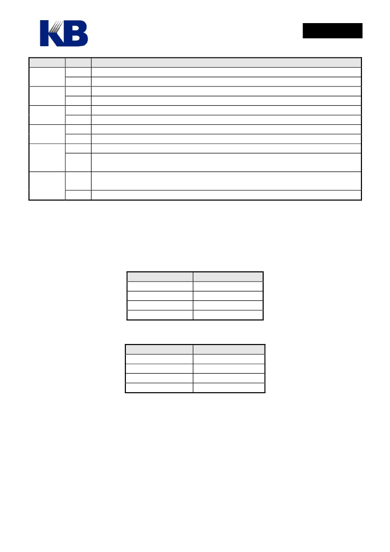
Field
Value
0
1
0
1
0
1
0
1
0
Function
LCD power system enabled.
LCD power system disabled.
Internal Charge-pump doesn’t accelerate to charge the capacitor.
Internal Charge-pump accelerates to charge the capacitor.
Disable internal bias network buffer
Enable internal bias network buffer
Reset GRAY palette register pointer by write ‘0’ to CLR_P bit.
No effect on GRAY palette register pointer
normal display
LCD display blanked. The COM signals of LCD driver output inactive levels
(LVL4 and LVL1) while SEG signals output normal display patterns.
LCD driver disabled, LCD driver has no output signal and LVL1 ~ LVL5 is pulled
up to VDD
LCD driver master control enabled
POWDN
PAcc
BUFE
CLR_GP
BLANK
1
0
LCDE
1
Bias Setting:
Different duties require different bias settings. There is some theoretical correspondence
between the Duty and Bias Setting. However, it is better to use it as starting point and adjust it with real
LCD panel connected to it to determine the final setting. The theoretic relationship between the duty and
bias setting is as the following table: However, the actual bias setting should be determined based on the
best visual effect given when the target LCD panel is connected.
Duty Cycle
32 duty
48 duty
64 duty
80 duty
Normal Bias Setting
1/7
1/8
1/9
1/10
The bias setting is made by mask option MO_LBSR[1..0].
MO_LBSR[1..0]
00
01
10
11
Bias Setting
1/7
1/8
1/9
1/10
Please note that LCD driver must be turned off before the IC goes into sleep mode. That means user must
clear the bit 0 of LCDC to turn off LCD driving circuit before setting bit6 of OP1 to enter sleep mode.
Large current might happen if the procedure is not followed. Please note that LCD driver uses slow clock
as clock source. The LCD display will not display normally if it works in Fast clock only mode because
the LCD refresh action is too fast. The LCD power system shall be enabled by set POWDN to ‘1’ before
the LCD display is enabled. In order to accelerate the capacitor charging, the “PAcc” bit shall be set when
the LCD power system is initialized and then “PAcc” can be cleared when the LCD power system is
stable.
相關(guān)PDF資料 |
PDF描述 |
|---|---|
| HE85750 | 8-bit Micro-controller |
| HE89410 | 8-BIT MICRO-CONTROLLER |
| HE89810 | 8-BIT MICRO-CONTROLLER |
| HE89820 | 8-BIT MICRO-CONTROLLER |
| HE89A20 | 8-BIT MICRO-CONTROLLER |
相關(guān)代理商/技術(shù)參數(shù) |
參數(shù)描述 |
|---|---|
| HE850 | 制造商:HVPSI 制造商全稱:High Voltage Power Solutions, Inc. 功能描述:SECONDARY SURGE "LIGHTNING" ARRESTER |
| HE8550 | 制造商:HSMC 制造商全稱:HSMC 功能描述:PNP EPITAXIAL PLANAR TRANSISTOR |
| HE8550_05 | 制造商:UTC-IC 制造商全稱:UTC-IC 功能描述:LOW VOLTAGE HIGH CURRENT SMALL SIGNAL PNP TRANSISTOR |
| HE8550_10 | 制造商:UTC-IC 制造商全稱:UTC-IC 功能描述:LOW VOLTAGE HIGH CURRENT SMALL SIGNAL PNP TRANSISTOR |
| HE8550-C-AB3-B | 制造商:UTC-IC 制造商全稱:UTC-IC 功能描述:LOW VOLTAGE HIGH CURRENT SMALL SIGNAL PNP TRANSISTOR |
發(fā)布緊急采購,3分鐘左右您將得到回復(fù)。