- 您現(xiàn)在的位置:買賣IC網(wǎng) > PDF目錄384403 > HFA3763 (Intersil Corporation) 288 MACROCELL 3.3 VOLT ISP CPLD PDF資料下載
參數(shù)資料
| 型號(hào): | HFA3763 |
| 廠商: | Intersil Corporation |
| 英文描述: | 288 MACROCELL 3.3 VOLT ISP CPLD |
| 中文描述: | 400MHz的正交調(diào)制器和AGC |
| 文件頁(yè)數(shù): | 4/10頁(yè) |
| 文件大小: | 72K |
| 代理商: | HFA3763 |
4-4
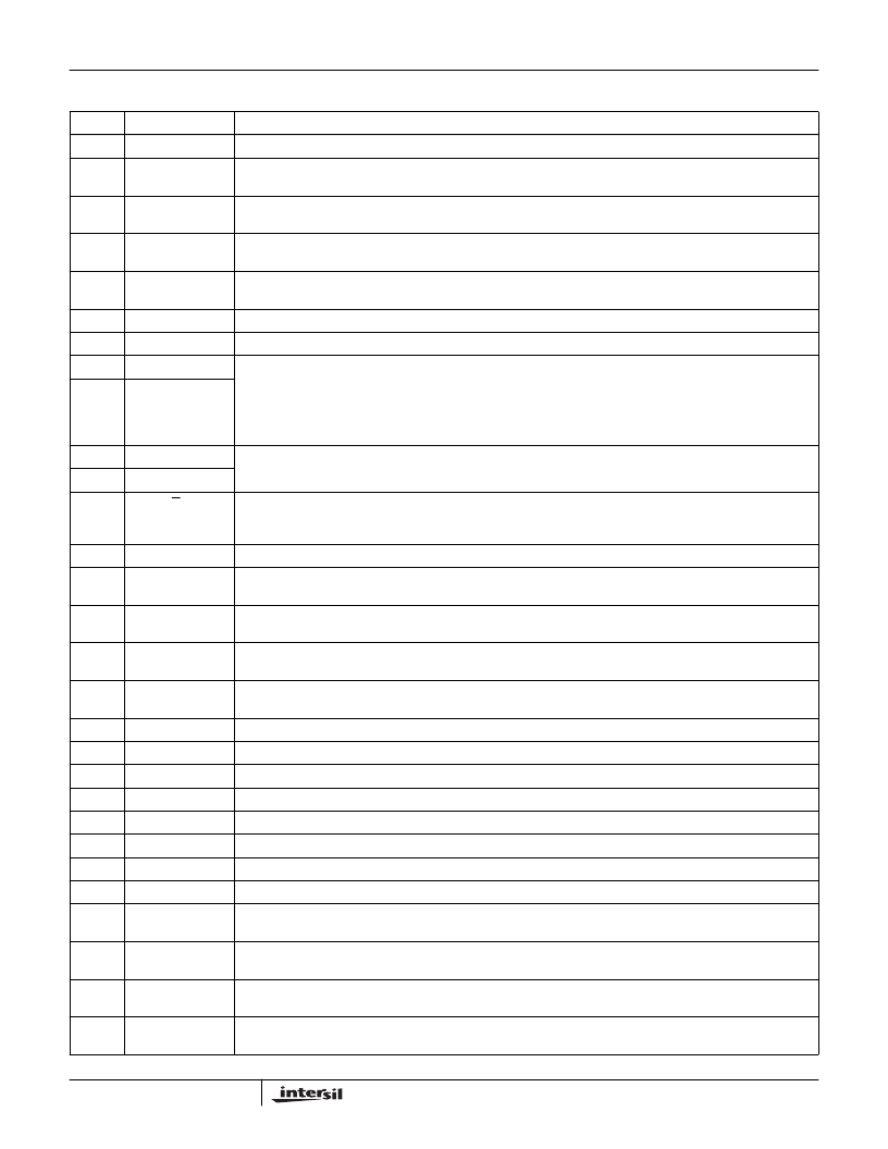
Pin Descriptions
PIN
SYMBOL
DESCRIPTION
9
LPF_V
CC
Supply pin for the Low pass filter. Use high quality decoupling capacitors right at the pin.
10
2V REF
Stable 2V reference voltage output for external applications. Loading must be higher than 10k
. A bypass
capacitor of at least 0.1
μ
F is required.
11
LPF_BYP
Internal reference bypass pin. This is the common voltage (V
CM
) used for the LPF digital thresholds. Requires
0.1
μ
F decoupling capacitor.
12
LPF_TXI_In
Low pass filter in phase (I) channel transmit input. Conventional or attenuated direct coupling is required for digital
inputs. AC couple for analog input.
13
LPF_TXQ_In
Low pass filter quadrature (Q) channel transmit input. Conventional or attenuated direct coupling is required for
digital inputs. AC couple for analog input.
14
NC
Connected internally for test purpose. Leave this pin floating.
15
NC
Connected internally for test purpose. Leave this pin floating.
16
LPF_Sel1
Digital control input pins. Selects four programmed cut off frequencies for the transmit channel. Tuning speed from
one cutoff to another is less than 1
μ
s.
SEL1
LO
LO
SEL0
LO
HI
CUTOFF FREQUENCY
2.2MHz
4.4MHz
SEL1
HI
HI
SEL0
LO
HI
CUTOFF FREQUENCY
8.8MHz
17.6MHz
17
LPF_Sel0
18
LPF_Tune1
These two pins are used to fine tune the Low pass filter cutoff frequency. A resistor connected between the two
pins (R
TUNE
) will fine tune the transmit filters. Refer to the tuning equation in the LPF AC specifications.
19
LPF_Tune0
20
TX D or A
Selects the configuration of the Transmit baseband input for either Digital or Analog (500mV
P-P
max).
Tie to a High for Analog and Ground for Digital inputs. Requires decoupling capacitor for analog and a simple direct
coupled attenuator for digital inputs.
22
LPF_TX_PE
Digital input control pin to enable the LPF transmit mode of operation. Enable logic level is High.
23
LPF_TXQ-
Negative output of the transmit Low pass filter, quadrature channel. AC coupling is required. Normally connects to
the inverting input of the quadrature Modulator (Mod_TXQ-), pin 40.
24
LPF_TXQ+
Positive output of the transmit Low pass filter, quadrature channel. AC coupling is required. Normally connects to
the non inverting input of the quadrature Modulator (Mod_TXQ+), pin 39.
25
LPF_TXI-
Negative output of the transmit Low pass filter, in phase channel. AC coupling is required. Normally connects to
the inverting input of the in phase Modulator (Mod_TXI-), pin 38.
26
LPF_TXI+
Positive output of the transmit Low pass filter, in phase channel. AC coupling is required. Normally connects to the
non inverting input of the in phase Modulator (Mod_TXI+), pin 37.
27
NC
Connected internally for test purpose. Leave this pin floating.
28
NC
Connected internally for test purpose. Leave this pin floating.
29
NC
Connected internally for test purpose. Leave this pin floating.
30
NC
Connected internally for test purpose. Leave this pin floating.
33
NC
Connected internally for test purpose. Leave this pin floating.
34
NC
Connected internally for test purpose. Leave this pin floating.
35
NC
Connected internally for test purpose. Leave this pin floating.
36
NC
Connected internally for test purpose. Leave this pin floating.
37
Mod_TXI+
In phase modulator non inverting input. AC coupling is required. This input is normally coupled to the Low pass
filter positive output (LPF_TXI+), pin 26.
38
Mod_TXI-
In phase modulator inverting input. AC coupling is required. This input is normally coupled to the Low pass filter
negative output (LPF_TXI-), pin 25.
39
Mod_TXQ+
Quadrature modulator non inverting input. AC coupling is required. This input is normally coupled to the Low pass
filter positive output (LPF_TXQ+), pin 24.
40
Mod_TXQ-
Quadrature modulator inverting input. AC coupling is required. This input is normally coupled to the Low pass filter
negative output (LPF_TXQ-), pin 23.
HFA3763
相關(guān)PDF資料 |
PDF描述 |
|---|---|
| HFA3763IN | 288 MACROCELL 3.3 VOLT ISP CPLD |
| HFA3767 | 288 MACROCELL 3.3 VOLT ISP CPLD |
| HFA3767IA | 130MHz CDMA/AMPS Quadrature Modulator and AGC |
| HFA3767IA96 | 130MHz CDMA/AMPS Quadrature Modulator and AGC |
| HFA3824 | () |
相關(guān)代理商/技術(shù)參數(shù) |
參數(shù)描述 |
|---|---|
| HFA3763IN | 制造商:INTERSIL 制造商全稱:Intersil Corporation 功能描述:400MHz Quadrature Modulator and AGC |
| HFA3763IN WAF | 制造商:Harris Corporation 功能描述: |
| HFA3765 | 制造商:INTERSIL 制造商全稱:Intersil Corporation 功能描述:AGC and Quadrature IF Demodulator |
| HFA3765IA | 制造商:INTERSIL 制造商全稱:Intersil Corporation 功能描述:AGC and Quadrature IF Demodulator |
| HFA3765IA WAF | 制造商:Harris Corporation 功能描述: |
發(fā)布緊急采購(gòu),3分鐘左右您將得到回復(fù)。