- 您現(xiàn)在的位置:買賣IC網(wǎng) > PDF目錄384443 > HS1-82C55ARH-8 (HARRIS SEMICONDUCTOR) Radiation Hardened CMOS Programmable Peripheral Interface PDF資料下載
參數(shù)資料
| 型號(hào): | HS1-82C55ARH-8 |
| 廠商: | HARRIS SEMICONDUCTOR |
| 元件分類: | 微控制器/微處理器 |
| 英文描述: | Radiation Hardened CMOS Programmable Peripheral Interface |
| 中文描述: | 24 I/O, PIA-GENERAL PURPOSE, CDIP40 |
| 文件頁(yè)數(shù): | 13/23頁(yè) |
| 文件大小: | 165K |
| 代理商: | HS1-82C55ARH-8 |
第1頁(yè)第2頁(yè)第3頁(yè)第4頁(yè)第5頁(yè)第6頁(yè)第7頁(yè)第8頁(yè)第9頁(yè)第10頁(yè)第11頁(yè)第12頁(yè)當(dāng)前第13頁(yè)第14頁(yè)第15頁(yè)第16頁(yè)第17頁(yè)第18頁(yè)第19頁(yè)第20頁(yè)第21頁(yè)第22頁(yè)第23頁(yè)
982
HS-82C55ARH
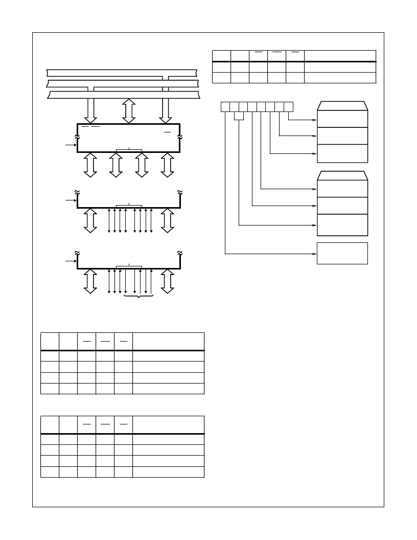
Control Word will always be in the format illustrated in Figure
11 with Bit D7 high to indicate Control Word Mode Informa-
tion.
FIGURE 10. BASIC MODE DEFINITIONS & BUS INTERFACE
TABLE 1.
A1
A0
RD
WR
CS
INPUT OPERATION
(READ)
0
0
0
1
0
Port A - Data Bus
0
1
0
1
0
Port B - Data Bus
1
0
0
1
0
Port C - Data Bus
1
1
0
1
0
Control Word - Data Bus
TABLE 2.
A1
A0
RD
WR
CS
OUTPUT OPERATION
(WRITE)
0
0
1
0
0
Data Bus - Port A
0
1
1
0
0
Data Bus - Port B
1
0
1
0
0
Data Bus - Port C
1
1
1
0
0
Data Bus - Control Word
RD, WR
D7 - D0
A0 - A1
CS
B
C
A
8
4
8
4
I/O
I/O
I/O
I/O
PB7 - PB0 PC3 - PC0 PC7 - PC4 PA7 - PA0
MODE 0
DATA BUS
CONTROL BUS
ADDRESS BUS
B
C
A
8
8
I/O
I/O
PB7 - PB0
PA7 - PA0
MODE 1
CONTROL
OR I/O
CONTROL
OR I/O
B
C
A
8
8
I/O
BIDIREC-
TIONAL
PB7 - PB0
PA7 - PA0
MODE 2
I/O
CONTROL
FIGURE 11. MODE SET CONTROL WORD FORMAT
Mode Selection
There are three basic modes of operation that can be
selected by the system software:
Mode 0 - Basic Input/Output
Mode 1 - Strobed Input/Output
Mode 2 - Bidirectional Bus
When the RESET input goes “high”, all ports will be set to
the input mode with all 24 port lines held at the logic “one”
level by internal bus hold devices. After reset, the HS-
82C55ARH can remain in the input mode with no additional
initialization required. This eliminates the need for pullup or
pulldown resistors in all CMOS designs. During the
execution of the system program, any of the other modes
may be selected using a single output instruction. This
allows a single HS-82C55ARH to service a variety of
peripheral devices with a simple software maintenance
routine.
The modes for Port A and Port B can be separately defined
while Port C is divided into two portions as required by the
Port A and Port B definitions. All of the output registers,
including the status register, will be reset whenever the
mode is changed. Modes may be combined so that their
functional definition can be “tailored” to almost any I/O struc-
ture. For instance: Group B can be programmed in Mode 0
to monitor simple switch closings or display computational
results, Group A could be programmed in Mode 1 to monitor
a keyboard or tape recorder on an interrupt-driven basis.
TABLE 3.
A1
A0
RD
WR
CS
DISABLE FUNCTION
X
X
X
X
1
Data Bus - 3-State
X
X
1
1
0
Data Bus - 3-State
D7 D6 D5 D4 D3 D2 D1 D0
CONTROL WORD
GROUP B
PORT C (LOWER)
1 = INPUT
0 = OUTPUT
PORT B
1 = INPUT
0 = OUTPUT
MODE SELECTION
0 = MODE 0
1 = MODE 1
GROUP A
PORT C (UPPER)
1 = INPUT
0 = OUTPUT
PORT A
1 = INPUT
0 = OUTPUT
MODE SELECTION
00 = MODE 0
01 = MODE 1
1X = MODE 2
MODE SET FLAG
1 = ACTIVE
Spec Number
518060
相關(guān)PDF資料 |
PDF描述 |
|---|---|
| HS9-2100RH | Radiation Hardened High Frequency Half Bridge Driver |
| HS-2100RH | Radiation Hardened High Frequency Half Bridge Driver(抗輻射高頻半橋N勾道MOSFET驅(qū)動(dòng)器) |
| HS9-2100RH-8 | Radiation Hardened High Frequency Half Bridge Driver |
| HS9-2100RH-Q | Radiation Hardened High Frequency Half Bridge Driver |
| HS9-22620RH | Rad Hard Dual, Wideband, High Input Impedance Uncompensated Operational Amplifier |
相關(guān)代理商/技術(shù)參數(shù) |
參數(shù)描述 |
|---|---|
| HS1-82C55ARH-Q | 制造商:Intersil Corporation 功能描述:PERIPHERAL INTRFC 40CDIP - Rail/Tube |
| HS1-82C59ARH-8 | 制造商:未知廠家 制造商全稱:未知廠家 功能描述:Interrupt Controller |
| HS1-82C85RH | 制造商:INTERSIL 制造商全稱:Intersil Corporation 功能描述:Radiation Hardened CMOS Static Clock Controller/Generator |
| HS1-82C85RH-8 | 制造商:Intersil Corporation 功能描述:CLOCK CNTRLR/GENERATOR 24PIN SBDIP - Rail/Tube |
| HS1-82C85RH-Q | 制造商:Intersil Corporation 功能描述:CLOCK CNTRLR/GENERATOR 24PIN SBDIP - Rail/Tube |
發(fā)布緊急采購(gòu),3分鐘左右您將得到回復(fù)。