- 您現(xiàn)在的位置:買賣IC網(wǎng) > PDF目錄384443 > HS1-82C55ARH-8 (HARRIS SEMICONDUCTOR) Radiation Hardened CMOS Programmable Peripheral Interface PDF資料下載
參數(shù)資料
| 型號: | HS1-82C55ARH-8 |
| 廠商: | HARRIS SEMICONDUCTOR |
| 元件分類: | 微控制器/微處理器 |
| 英文描述: | Radiation Hardened CMOS Programmable Peripheral Interface |
| 中文描述: | 24 I/O, PIA-GENERAL PURPOSE, CDIP40 |
| 文件頁數(shù): | 18/23頁 |
| 文件大小: | 165K |
| 代理商: | HS1-82C55ARH-8 |
987
HS-82C55ARH
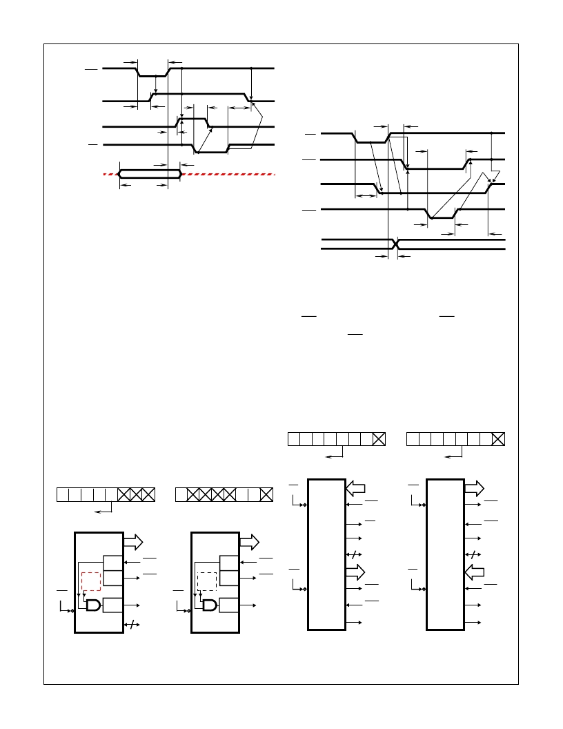
FIGURE 16. MODE 1 (STROBED INPUT)
Output Control Signal Definition
OBF (Output Buffer Full F/F)
The OBF output will go “l(fā)ow” to indicate that the CPU has
written data out to the specified port. This does not mean
valid data is sent out of the port at this time since OBF can
go true before data is available. Data is guaranteed valid at
the rising edge of OBF. See Note 1. The OBF F/F will be set
by the rising edge of the WR input and reset by ACK input
being low.
ACK (Acknowledge Input)
A “l(fā)ow” on this input informs the HS-82C55ARH that the data
from Port A or Port B is ready to be accepted. In essence, a
response from the peripheral device indicating that it is
ready to accept data. See Note 1.
INTR (Interrupt Request)
A “high” on this output can be used to interrupt the CPU
when an output device has accepted data transmitted by the
CPU. INTR is set by the rising edge of ACK and reset by the
falling edge of WR.
FIGURE 17. MODE 1 OUTPUT
STB
IBF
INTR
RD
INPUT FROM
PERIPHERAL
TSLSH
TSLIH
TSHPX
TPVSH
TRHIL
TRLNL
TSHNH
INTE
A
D7 D6 D5 D4 D3 D2 D1 D0
1
CONTROL WORD
MODE 1 (PORT B)
1
0
PA7 - PA0
PC7
PC6
PC3
PC4, 5
WR
8
OBF
A
ACK
A
INTR
A
I/O
2
INTE
B
PB7 - PB0
PC1
PC2
PC0
WR
8
OBF
B
ACK
B
INTR
B
D7 D6 D5 D4 D3 D2 D1 D0
1
0
1
0
1/0
CONTROL WORD
PC4, 5
1 = INPUT
0 = OUTPUT
MODE 1 (PORT A)
INTE A
Controlled by Bit Set/Reset of PC6.
INTE B
Controlled by Bit Set/Reset of PC2.
FIGURE 18. MODE 1 (STROBED OUTPUT)
NOTE:
1. To strobe data into the peripheral device, the user must operate
the strobe line in a hand shaking mode. The user needs to send
OBF to the peripheral device, generate an ACK from the periph-
eral device and then latch data into the peripheral device on the
rising edge of OBF.
Combinations of Mode 1: Port A and Port B can be individu-
ally defined as input or output in Mode 1 to support a wide
variety of strobed I/O applications.
FIGURE 19. COMBINATIONS OF MODE 1
WR
OBF
INTR
ACK
OUTPUT
TWLNL
TWHOL
TKHOL
TWHPV
TKLKH
TKHNH
D7 D6 D5 D4 D3 D2 D1 D0
1
CONTROL WORD
PORT A (STROBED INPUT)
PORT B (STROBED OUTPUT)
1
0
0
1
1
1/0
PC6, 7
1 = INPUT
0 = OUTPUT
PA7 - PA0
PC4
PC5
PC6, 7
WR
8
STB A
IBF A
INTR A
PC3
PB7 - PB0
PC1
PC2
PC0
I/O
OBF B
ACK B
INTR B
8
2
RD
D7 D6 D5 D4 D3 D2 D1 D0
1
CONTROL WORD
PORT A (STROBED OUTPUT)
PORT B (STROBED INPUT)
1
1
0
1
0
1/0
PC4, 5
1 = INPUT
0 = OUTPUT
PA7 - PA0
PC7
PC6
PC4, 5
RD
8
OBF A
ACK A
INTR A
PC3
PB7 - PB0
PC2
PC1
PC0
I/O
STB B
IBF B
INTR B
8
2
WR
Spec Number
518060
相關PDF資料 |
PDF描述 |
|---|---|
| HS9-2100RH | Radiation Hardened High Frequency Half Bridge Driver |
| HS-2100RH | Radiation Hardened High Frequency Half Bridge Driver(抗輻射高頻半橋N勾道MOSFET驅動器) |
| HS9-2100RH-8 | Radiation Hardened High Frequency Half Bridge Driver |
| HS9-2100RH-Q | Radiation Hardened High Frequency Half Bridge Driver |
| HS9-22620RH | Rad Hard Dual, Wideband, High Input Impedance Uncompensated Operational Amplifier |
相關代理商/技術參數(shù) |
參數(shù)描述 |
|---|---|
| HS1-82C55ARH-Q | 制造商:Intersil Corporation 功能描述:PERIPHERAL INTRFC 40CDIP - Rail/Tube |
| HS1-82C59ARH-8 | 制造商:未知廠家 制造商全稱:未知廠家 功能描述:Interrupt Controller |
| HS1-82C85RH | 制造商:INTERSIL 制造商全稱:Intersil Corporation 功能描述:Radiation Hardened CMOS Static Clock Controller/Generator |
| HS1-82C85RH-8 | 制造商:Intersil Corporation 功能描述:CLOCK CNTRLR/GENERATOR 24PIN SBDIP - Rail/Tube |
| HS1-82C85RH-Q | 制造商:Intersil Corporation 功能描述:CLOCK CNTRLR/GENERATOR 24PIN SBDIP - Rail/Tube |
發(fā)布緊急采購,3分鐘左右您將得到回復。