- 您現(xiàn)在的位置:買賣IC網(wǎng) > PDF目錄379204 > IBM11N8735B (IBM Microeletronics) 8M x 72 DRAM MODULE(8M x 72動態(tài)RAM模塊) PDF資料下載
參數(shù)資料
| 型號: | IBM11N8735B |
| 廠商: | IBM Microeletronics |
| 英文描述: | 8M x 72 DRAM MODULE(8M x 72動態(tài)RAM模塊) |
| 中文描述: | 8米× 72 DRAM模塊(8米× 72動態(tài)內(nèi)存模塊) |
| 文件頁數(shù): | 28/31頁 |
| 文件大小: | 626K |
| 代理商: | IBM11N8735B |
第1頁第2頁第3頁第4頁第5頁第6頁第7頁第8頁第9頁第10頁第11頁第12頁第13頁第14頁第15頁第16頁第17頁第18頁第19頁第20頁第21頁第22頁第23頁第24頁第25頁第26頁第27頁當(dāng)前第28頁第29頁第30頁第31頁
IBM Corporation. All rights reserved.
Use is further subject to the provisions at the end of this document.
Page 28 of 33
75H1747
SA14-4624-04
Revised 3/97
IBM11N8645B
IBM11N8645C
8M x 64/72 DRAM MODULE
IBM11N8735B
IBM11N8735C
Presence Detect Operation
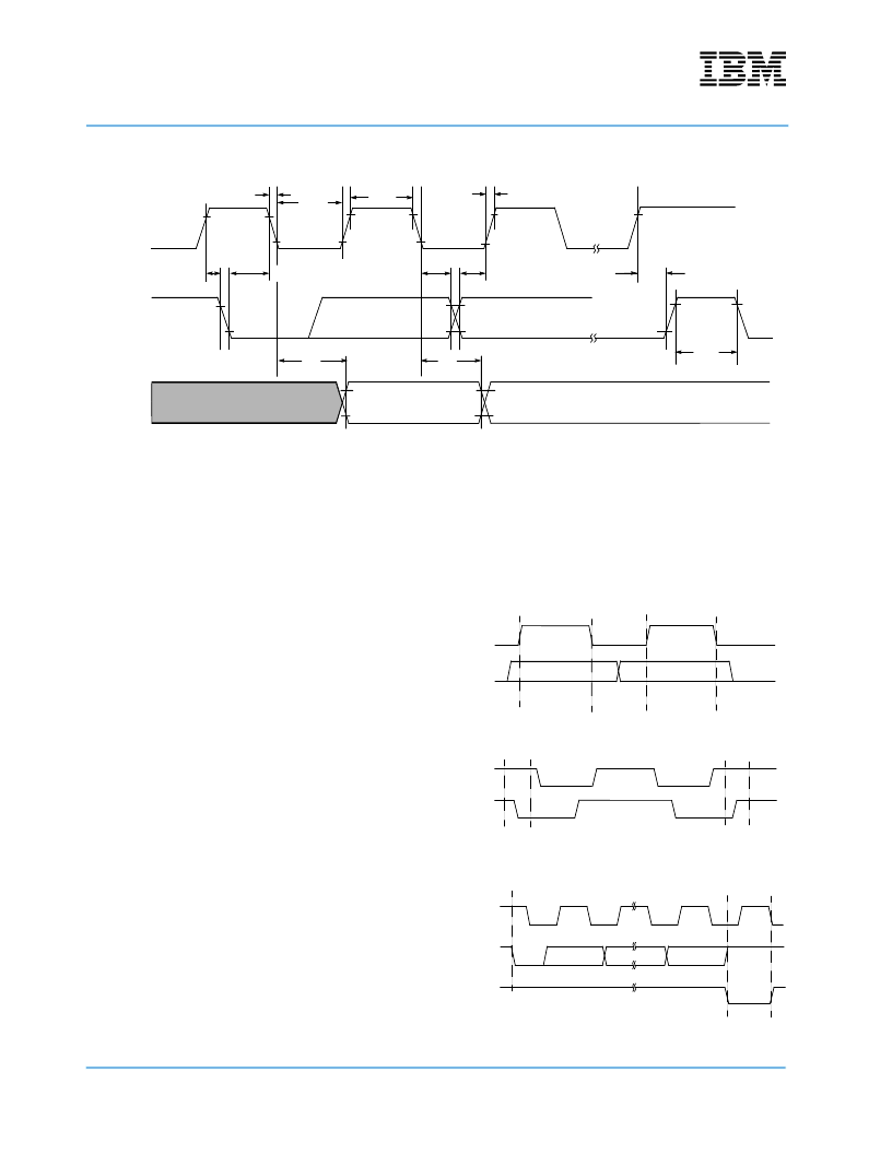
Clock and Data Conventions
: Data states on the
SDA line can change only during SCL low. SDA
state changes during SCL HIGH are reserved for
indicating start and stop conditions (Figure 1 & Fig-
ure 2).
Start Condition
: All commands are preceded by
the start condition, which is a HIGH to LOW transi-
tion of SDA when SCL is high. The serial PD device
continuously monitors the SDA and SCL lines for
the start condition and will not respond to any com-
mand until this condition has been met.
Stop Condition
: All communications are terminated
by a stop condition, which is a LOW to HIGH transi-
tion of SDA when SCL is HIGH. The stop condition
is also used to place the serial PD device into
standby power mode.
Acknowledge
: Acknowledge is a software conven-
tion used to indicate successful data transfers. The
transmitting device, either master or slave, will
release the bus after transmitting eight bits. During
the ninth clock cycle the receiver will pull the SDA
line LOW to acknowledge that it received the eight
bits of data (Figure 3).
The PD device will always respond with an acknowl-
edge after recognition of a start condition and its
slave address. If both the device and a write opera-
tion have been selected, The PD device, will respond
with an acknowledge after the receipt of each subse-
quent eight bit word. In the read mode the PD device
will transmit eight bits of data, release the SDA line
and monitor the line for an
acknowledge. If an acknowledge is detected and no
stop condition is generated by the master, the slave
will continue to transmit data. If an acknowledge is
not detected, the slave will terminate further data
transmissions and await the stop condition to return
to standby power mode.
Presence Detect (EEPROM) Bus Timing
SCL
SDA
IN
t
SU:STO
t
HD:STA
t
SU:STA
t
AA
SDA
OUT
t
F
t
LOW
t
HIGH
t
R
t
SU:DAT
t
HD:DAT
t
BUF
t
DH
Figure 1. Data Window
Figure 2. Definition of Start & Stop
Figure 3. Acknowledge Response From Receiver
SCL
SDA
Data
Change
Data Stable
Data Stable
SCL
SDA
Start
Bit
Stop
Bit
Acknowledge
SCL from
Master
Data Output
from Trans
Data Output
from Receiver
8
9
Discontinued (9/98 - last order; 3/99 last ship)
相關(guān)PDF資料 |
PDF描述 |
|---|---|
| IBM11N8735C | 8M x 72 DRAM MODULE(8M x 72動態(tài)RAM模塊) |
| IBM11N8645H | 8M x 64 DRAM Module(8M x 64 動態(tài)RAM模塊) |
| IBM11N8735H | 8M x 72 DRAM Module(8M x 72 動態(tài)RAM模塊) |
| IBM11N8845HB | 8M x 72 Chip-Kill Protect ECC-on-DIMM Module(8M x 72 帶糾錯代碼保護(hù)的小外形雙列直插動態(tài)RAM模塊) |
| IBM13M32734BCA | 32M x 72 2-Bank Registered SDRAM Module(32M x 72 2組寄存同步動態(tài)RAM模塊) |
相關(guān)代理商/技術(shù)參數(shù) |
參數(shù)描述 |
|---|---|
| IBM14H5481 | 制造商:AVED Memory Products 功能描述: |
| IBM14H5540 | 制造商:AVED MEMORY PRODUCTS 功能描述: 制造商:AVED Memory Products 功能描述: |
| IBM17R8251 | 制造商:AVED Memory Products 功能描述: |
| IBM17R8252 | 制造商:AVED Memory Products 功能描述: |
| IBM1805T | 制造商:Schneider Electric 功能描述:IBM1805T |
發(fā)布緊急采購,3分鐘左右您將得到回復(fù)。