- 您現(xiàn)在的位置:買賣IC網(wǎng) > PDF目錄379205 > IBM3209K3114 (IBM Microeletronics) IBM Packet Routing Switch Serial Interface Converter(IBM封裝路線選擇開關(guān)串行接口轉(zhuǎn)換器) PDF資料下載
參數(shù)資料
| 型號(hào): | IBM3209K3114 |
| 廠商: | IBM Microeletronics |
| 英文描述: | IBM Packet Routing Switch Serial Interface Converter(IBM封裝路線選擇開關(guān)串行接口轉(zhuǎn)換器) |
| 中文描述: | IBM的分組路由交換機(jī)串行接口轉(zhuǎn)換器(IBM的封裝路線選擇開關(guān)串行接口轉(zhuǎn)換器) |
| 文件頁數(shù): | 40/152頁 |
| 文件大小: | 2390K |
| 代理商: | IBM3209K3114 |
第1頁第2頁第3頁第4頁第5頁第6頁第7頁第8頁第9頁第10頁第11頁第12頁第13頁第14頁第15頁第16頁第17頁第18頁第19頁第20頁第21頁第22頁第23頁第24頁第25頁第26頁第27頁第28頁第29頁第30頁第31頁第32頁第33頁第34頁第35頁第36頁第37頁第38頁第39頁當(dāng)前第40頁第41頁第42頁第43頁第44頁第45頁第46頁第47頁第48頁第49頁第50頁第51頁第52頁第53頁第54頁第55頁第56頁第57頁第58頁第59頁第60頁第61頁第62頁第63頁第64頁第65頁第66頁第67頁第68頁第69頁第70頁第71頁第72頁第73頁第74頁第75頁第76頁第77頁第78頁第79頁第80頁第81頁第82頁第83頁第84頁第85頁第86頁第87頁第88頁第89頁第90頁第91頁第92頁第93頁第94頁第95頁第96頁第97頁第98頁第99頁第100頁第101頁第102頁第103頁第104頁第105頁第106頁第107頁第108頁第109頁第110頁第111頁第112頁第113頁第114頁第115頁第116頁第117頁第118頁第119頁第120頁第121頁第122頁第123頁第124頁第125頁第126頁第127頁第128頁第129頁第130頁第131頁第132頁第133頁第134頁第135頁第136頁第137頁第138頁第139頁第140頁第141頁第142頁第143頁第144頁第145頁第146頁第147頁第148頁第149頁第150頁第151頁第152頁
IBM3209K3114
IBM Packet Routing Switch Serial Interface Converter
Advance
Functional Description
Page 30 of 142
prssi.01
July 12, 2000
3.6.6 IBM Packet Routing Switch Serial Interface Converter (the converter) Switch Interface
3.7 Egress & Ingress Interface Diagnostic Functions
3.7.1 Loopbacks
Loopbacks are controlled through configuration registers
.
There are two possible paths, X and Y, for each
loopback, but an exclusive choice must be made and a path reset executed before the loopback is
performed. The IBM Packet Routing Switch Serial Interface Converter (the converter) supports two loopback
modes:
Protocol engine (PE) X/Y loopback: the PE sends and checks data and the grant mechanism must be
bypassed (forced to all ones through configuration register)
- Protocol engine X domain loopback (register @00 bit 0 set to '1')
- Protocol engine Y domain loopback (register @20 bit 0 set to '1')
Switch loopback: data is initiated from the switch and the switch control verifies the overall operation
- Switch X and Switch Y domain loopbacks: (register @C4 bit 1 set to '1'). Depending on the status of
the force path and select X/Y bits of registers A0 bits 21 and 22 respectively, it is possible to use
either the inService line or the select X/Y by means of bit 22 to decide which plane is selected. In the
latter case, plane X is used if set to '0' and plane Y is used if set to '1'.
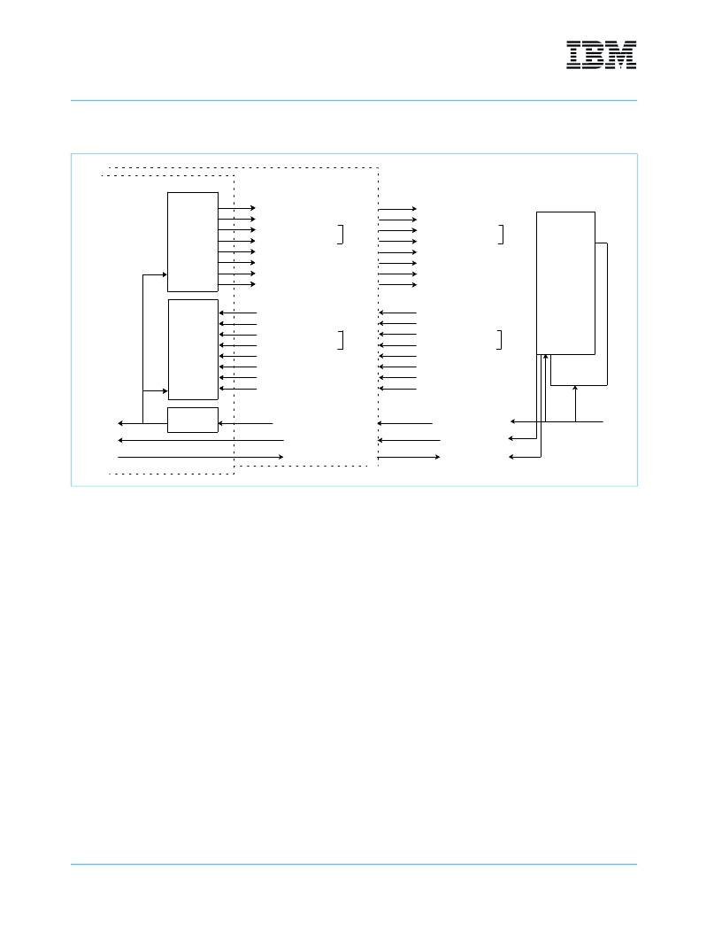
Figure 16: Converter Interface Lines
+/-Switch_X_CLK
MEM_GNT_X (3:0)
8 x DASL Pairs
+/-DASL_X_TX_0
+/-DASL_X_TX_1
+/-DASL_X_TX_2
+/-DASL_X_TX_3
+/-DASL_X_TX_4
+/-DASL_X_TX_5
+/-DASL_X_TX_6
+/-DASL_X_TX_7
PLL
Converter Path X
Converter Path Y
+/-Switch_Y_CLK
MEM_GNT_Y (3:0)
SEND_GNT_Y
SEND_GNT_X
+/-DASL_Y_RX_0
+/-DASL_Y_RX_1
+/-DASL_Y_RX_2
+/-DASL_Y_RX_3
+/-DASL_Y_RX_4
+/-DASL_Y_RX_5
+/-DASL_Y_RX_6
+/-DASL_Y_RX_7
+/-DASL_Y_TX_0
+/-DASL_Y_TX_1
+/-DASL_Y_TX_2
+/-DASL_Y_TX_3
+/-DASL_Y_TX_4
+/-DASL_Y_TX_5
+/-DASL_Y_TX_6
+/-DASL_Y_TX_7
L U
Chip 0
Chip 1
Switch Core Y
L U
Master
L U
Master
L U
Path X
Path X
8 x DASL Pairs
+/-DASL_X_RX_0
+/-DASL_X_RX_1
+/-DASL_X_RX_2
+/-DASL_X_RX_3
+/-DASL_X_RX_4
+/-DASL_X_RX_5
+/-DASL_X_RX_6
+/-DASL_X_RX_7
Master
Master
DASL
Egress
DASL
Ingress
IBM 28.4 G
Packet
Routing
Switch
相關(guān)PDF資料 |
PDF描述 |
|---|---|
| IBM32NPCXX1EPABBE66 | IBM Processor for Network Resources(異步轉(zhuǎn)換模式(ATM)32位微處理器(用于網(wǎng)絡(luò)資源管理)) |
| IBM39MPEGCS24DPFA16C | High Performance Audio/Video Decoder(高性能音頻/視頻譯碼器) |
| IBM39MPEGCS24PFA16C | High Performance Audio/Video Decoder(高性能音頻/視頻譯碼器) |
| IBM39STB130x0 | STB130x0 A/V Transport/Decoders(STB130x0 音頻/視頻的傳送譯碼器) |
| IBM42F10SNNAA20 | SFF-1063/1250N-SW PTH Serial Optical Transceiver(SFF-1063/1250N-SW PTH串行光纖收發(fā)器) |
相關(guān)代理商/技術(shù)參數(shù) |
參數(shù)描述 |
|---|---|
| IBM3209K4060 | 制造商:未知廠家 制造商全稱:未知廠家 功能描述:Telecom Switching Circuit |
| IBM3288H2848 | 制造商:未知廠家 制造商全稱:未知廠家 功能描述:Telecommunication IC |
| IBM32NPR100EXXCAB133 | 制造商:未知廠家 制造商全稱:未知廠家 功能描述:Microprocessor |
| IBM32NPR101EPXCAC133 | 制造商:未知廠家 制造商全稱:未知廠家 功能描述:Microprocessor |
| IBM35CPC945C03C-2 | 制造商:IBM 功能描述: |
發(fā)布緊急采購,3分鐘左右您將得到回復(fù)。