- 您現(xiàn)在的位置:買賣IC網(wǎng) > PDF目錄379205 > IBM42F21LNNAA10 (IBM Microeletronics) 1x Fibre Channel Small Form Factor PTH Transceiver(1x吉位光纖通道小外形PTH收發(fā)器) PDF資料下載
參數(shù)資料
| 型號: | IBM42F21LNNAA10 |
| 廠商: | IBM Microeletronics |
| 英文描述: | 1x Fibre Channel Small Form Factor PTH Transceiver(1x吉位光纖通道小外形PTH收發(fā)器) |
| 中文描述: | 1X的光纖通道纖巧甲狀旁腺收發(fā)器(1倍吉位光纖通道小外形甲狀旁腺收發(fā)器) |
| 文件頁數(shù): | 8/24頁 |
| 文件大?。?/td> | 210K |
| 代理商: | IBM42F21LNNAA10 |
IBM42F21SNNAA10
IBM42F21LNNAA10
2x / 1x Fibre Channel Small Form Factor PTH Transceiver
IBM42G21SNNAA10
IBM42G21LNNAA10
Page 8 of 23
08/15/00
Transmit Signal Interface
(from host to SFF-PTH-2125-SW/LW-2X5/2X6)
Symbol
Parameter
Min
Max.
Unit
Notes
V
o
PECL Amplitude
400
2000
mV
1
DJ
elec-xmit
PECL Deterministic Jitter
0.14
UI
2,4
TJ
elec-xmt
PECL Total Jitter
0.26
UI
2,4
PECL Rise/Fall
50
200
ps
3,4
PECL Differential Skew
20
ps
4
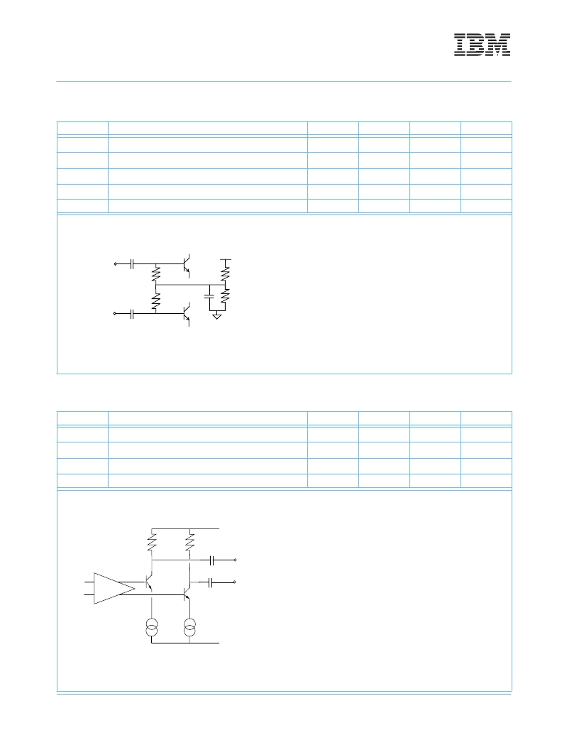
1. At 100
, differential peak-to-peak, the figure below shows the simplified circuit schematic for the SFF-PTH-2125-SW/LW-2X5/2X6
high-speed differential input lines. The PECL input data lines have AC coupling capacitors. The capacitors are not required on the
host card.
2. Deterministic jitter (DJ) and total jitter (TJ) values are measured according to the methods defined in [2]. Jitter values at the output
of a transmitter or receiver section assume worst case jitter values at its respective input. [1UI(Unit Interval)=470.6ps at 2.125Gb/s]
3. Rise and fall times are measured from 20 - 80%, 100
differential.
4. When in 1Gb/s mode the transceiver is compliant with 1G specifications as defined in [1].
Receive Signal Interface
(from SFF-PTH-2125-SW/LW-2X5/2X6 to host)
Symbol
Parameter
Min
Max.
Unit
Note(s)
V
o
PECL Amplitude
600
1000
mV
1
DJ
elec-rcv
PECL Deterministic Jitter
0.39
UI
2,3
TJ
elec-rcv
PECL Total Jitter
0.64
UI
2,3
PECL Differential Skew
102
ps
3
1. At 100
, differential peak-to-peak, the figure below shows the simplified circuit schematic for the SFF-PTH-2125-SW/LW-2X5/2X6
high-speed differential output lines. The PECL input data lines have AC coupling capacitors. The capacitors are not required on the
host card.
Rx_V
DD
50
50
2. Deterministic jitter (DJ) and total jitter (TJ) values are measured according to the methods defined in [2]. Jitter values at the output
of a transmitter or receiver section assume worst case jitter values at its respective input. [1UI(Unit Interval)=470.6ps at 2.125Gb/s]
3. When in 1Gb/s mode the transceiver is compliant with 1G specifications as defined in [1]. 1UI(Unit Interval)=941.2ps at
1.0625Gb/s)
V
DD
2.4K
50
50
3.8K
8pF
+Tx_DAT
-Tx_DAT
Rx_Gnd
...
+Rx_DAT
-Rx_DAT
相關(guān)PDF資料 |
PDF描述 |
|---|---|
| IBM42G21LNNAA10 | 1x Fibre Channel Small Form Factor PTH Transceiver(1x吉位光纖通道小外形PTH收發(fā)器) |
| IBM42G21SNNAA10 | 2x Fibre Channel Small Form Factor PTH Transceiver(2x吉位光纖通道小外形PTH收發(fā)器) |
| IBM42F21SNNAA10 | 2x Fibre Channel Small Form Factor PTH Transceiver(2x吉位光纖通道小外形PTH收發(fā)器) |
| IBM42M10LCYAA20 | 1063 MB/S Gigabit Link Module(1063 MB/S 吉位連接模塊(高性能集成光纖收發(fā)器)) |
| IBM42M10SCYAA10 | 1063 MB/S Gigabit Link Module(1063 MB/S 吉位連接模塊(高性能集成光纖收發(fā)器)) |
相關(guān)代理商/技術(shù)參數(shù) |
參數(shù)描述 |
|---|---|
| IBM42S10SNNAA20 | 制造商:IBM 功能描述:IC,DATACOM,ETHERNET TRANSCEIVER,XFO |
| IBM4MB01 | 制造商:AVED MEMORY PRODUCTS 功能描述: 制造商:AVED Memory Products 功能描述: |
| IBM63H2431-BRD | 制造商:AVED MEMORY PRODUCTS 功能描述: |
| IBM63H2469 | 制造商:AVED Memory Products 功能描述: |
| IBM64793 | 制造商:Harris Corporation 功能描述: |
發(fā)布緊急采購,3分鐘左右您將得到回復。