- 您現(xiàn)在的位置:買賣IC網(wǎng) > PDF目錄379219 > IMISM560BZT (CYPRESS SEMICONDUCTOR CORP) Spread Spectrum Clock Generator PDF資料下載
參數(shù)資料
| 型號(hào): | IMISM560BZT |
| 廠商: | CYPRESS SEMICONDUCTOR CORP |
| 元件分類: | XO, clock |
| 英文描述: | Spread Spectrum Clock Generator |
| 中文描述: | 108 MHz, OTHER CLOCK GENERATOR, PDSO8 |
| 封裝: | 0.150 INCH, MS-012, SOIC-8 |
| 文件頁(yè)數(shù): | 4/8頁(yè) |
| 文件大小: | 246K |
| 代理商: | IMISM560BZT |
SM560
Document #: 38-07020 Rev. *E
Page 4 of 8
Absolute Maximum Ratings
[1]
Supply Voltage (V
DD
):....................................–0.5V to +6.0V
DC Input Voltage:..................................–0.5V to VDD + 0.5V
Junction Temperature .................................–40°C to +140°C
Operating Temperature:...................................... 0°C to 70°C
Storage Temperature.................................. –65°C to +150°C
Static Discharge Voltage (ESD).......................... 2,000V-Min.
SSCG Theory of Operation
The SM560 is a PLL-type clock generator using a proprietary
Cypress design. By precisely controlling the bandwidth of the
output clock, the SM560 becomes a Low EMI clock generator.
The theory and detailed operation of the SM560 will be
discussed in the following sections.
EMI
All digital clocks generate unwanted energy in their harmonics.
Conventional digital clocks are square waves with a duty cycle
that is very close to 50%. Because of this 50/50-duty cycle,
digital clocks generate most of their harmonic energy in the
odd harmonics, i.e.; third, fifth, seventh, etc. It is possible to
reduce the amount of energy contained in the fundamental
and odd harmonics by increasing the bandwidth of the funda-
mental clock frequency. Conventional digital clocks have a
very high Q factor, which means that all of the energy at that
frequency is concentrated in a very narrow bandwidth, conse-
quently, higher energy peaks. Regulatory agencies test
Note:
1.
Single Power Supply:
The Voltage on any input or I/O pin cannot exceed the power pin during power up.
electronic equipment by the amount of peak energy radiated
from the equipment. By reducing the peak energy at the funda-
mental and harmonic frequencies, the equipment under test is
able to satisfy agency requirements for EMI. Conventional
methods of reducing EMI have been to use shielding, filtering,
multi-layer PCBs, etc. The SM560 uses the approach of
reducing the peak energy in the clock by increasing the clock
bandwidth, and lowering the Q.
SSCG
SSCG uses a patented technology of modulating the clock
over a very narrow bandwidth and controlled rate of change,
both peak and cycle to cycle. The SM560 takes a narrow band
digital reference clock in the range of 25–108 MHz and
produces a clock that sweeps between a controlled start and
stop frequency and precise rate of change. To understand
what happens to a clock when SSCG is applied, consider a
65-MHz clock with a 50% duty cycle. From a 65-MHz clock we
know the following:
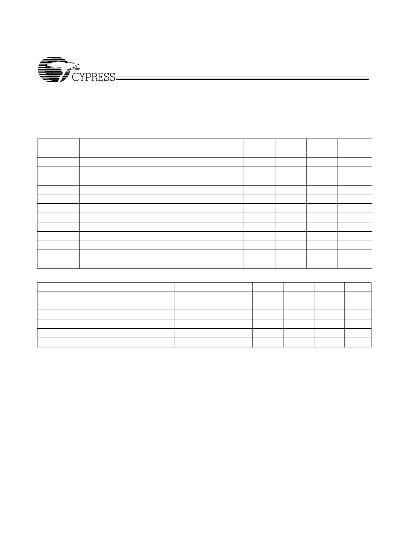
Table 2. DC Electrical Characteristics:
V
DD
= 3.3V, Temp. = 25°C and C
L
(Pin 4) = 15 pF, unless otherwise noted
Parameter
Description
Conditions
V
DD
Power Supply Range
±10%
V
INH
Input High Voltage
S0 and S1 only
V
INM
Input Middle Voltage
S0 and S1 only
V
INL
Input Low Voltage
S0 and S1 only
V
OH1
Output High Voltage
I
OH
= 6 mA
V
OH2
Output High Voltage
I
OH
= 20 mA
V
OL1
Output Low Voltage
I
OH
= 6 mA
V
OL2
Output Low Voltage
I
OH
= 20 mA
Cin1
Input Capacitance
Xin/CLK (Pin 1)
Cin2
Input Capacitance
Xout (Pin 8)
Cin2
Input Capacitance
S0, S1, SSCC (Pins 7,6,5)
I
DD1
Power Supply Current
F
IN
= 40 MHz
I
DD2
Power Supply Current
F
IN
= 65 MHz
Min.
2.97
0.85V
DD
0.40V
DD
0.0
2.4
2.0
Typ.
3.3
V
DD
0.50V
DD
0.0
Max.
3.63
V
DD
0.60V
DD
0.15V
DD
Unit
V
V
V
V
V
V
V
V
pF
pF
pF
mA
mA
0.4
1.2
5
10
5
40
45
3
6
3
4
8
4
30
35
Table 3. Electrical Timing Characteristics:
V
DD
= 3.3V, T = 25°C and C
L
= 15 pF, unless otherwise noted
Parameter
Description
ICLKFR
Input Clock Frequency Range
V
DD
= 3.30V
Trise
Clock Rise Time (Pin 4)
SSCLK1 @ 0.4 – 2.4V
Tfall
Clock Fall Time (Pin 4)
SSCLK1 @ 0.4 – 2.4V
DTYin
Input Clock Duty Cycle
XIN/CLK (Pin 1)
DTYout
Output Clock Duty Cycle
SSCLK1 (Pin 4)
JCC
Cycle-to-Cycle Jitter
Fin = 25 – 108 MHz
Conditions
Min.
25
1.2
1.2
20
45
-
Typ.
Max.
108
1.6
1.6
80
55
175
Unit
MHz
ns
ns
%
%
ps
1.4
1.4
50
50
125
相關(guān)PDF資料 |
PDF描述 |
|---|---|
| IN12V1A | Inverters 5 Volt, 12 Volt |
| IN5V1 | Inverters 5 Volt, 12 Volt |
| IN5V2A | Inverters 5 Volt, 12 Volt |
| IN12V2A | Inverters 5 Volt, 12 Volt |
| IN145403 | DRIVERS/RECEIVERS RS-232-E |
相關(guān)代理商/技術(shù)參數(shù) |
參數(shù)描述 |
|---|---|
| IMISM561 | 制造商:CYPRESS 制造商全稱:Cypress Semiconductor 功能描述:Spread Spectrum Clock Generator |
| IMISM561BZ | 制造商:Rochester Electronics LLC 功能描述:- Bulk 制造商:Cypress Semiconductor 功能描述: |
| IMISM561BZT | 制造商:CYPRESS 制造商全稱:Cypress Semiconductor 功能描述:Spread Spectrum Clock Generator |
| IMISM561Z | 制造商:International Microcircuits (IMI) / Cypress 功能描述: |
| IMISM562BZ | 制造商:Cypress Semiconductor 功能描述:PLL Clock Generator Single 54MHz to 200MHz 8-Pin SOIC |
發(fā)布緊急采購(gòu),3分鐘左右您將得到回復(fù)。