- 您現(xiàn)在的位置:買賣IC網(wǎng) > PDF目錄379243 > ISL9R18120S3S (FAIRCHILD SEMICONDUCTOR CORP) 18A, 1200V Stealth⑩ Diode PDF資料下載
參數(shù)資料
| 型號: | ISL9R18120S3S |
| 廠商: | FAIRCHILD SEMICONDUCTOR CORP |
| 元件分類: | 參考電壓二極管 |
| 英文描述: | 18A, 1200V Stealth⑩ Diode |
| 中文描述: | 18 A, 1200 V, SILICON, RECTIFIER DIODE, TO-263AB |
| 封裝: | TO-263AB, 3 PIN |
| 文件頁數(shù): | 1/6頁 |
| 文件大小: | 161K |
| 代理商: | ISL9R18120S3S |
2002 Fairchild Semiconductor Corporation
May 2002
I
ISL9R18120G2 / ISL9R18120P2 / ISL9R18120S3S Rev. A
ISL9R18120G2 / ISL9R18120P2 / ISL9R18120S3S
18A, 1200V Stealth Diode
General Description
The ISL9R18120G2, ISL9R18120P2 and ISL9R18120S3S are
Stealth diodes optimized for low loss performance in high
frequency hard switched applications. The Stealth family
exhibits low reverse recovery current (I
RM(REC)
) and
exceptionally soft recovery under typical operating conditions.
This device is intended for use as a free wheeling or boost
diode in power supplies and other power switching
applications. The low I
RM(REC)
and short t
a
phase reduce loss
in switching transistors. The soft recovery minimizes ringing,
expanding the range of conditions under which the diode may
be operated without the use of additional snubber circuitry.
Consider using the Stealth diode with a 1200V NPT IGBT to
provide the most efficient and highest power density design at
lower cost.
Formerly developmental type TA49414
.
Features
Soft Recovery . . . . . . . . . . . . . . . . . . . . . . . .t
b
/ t
a
> 5.0
Fast Recovery . . . . . . . . . . . . . . . . . . . . . . . . . t
rr
< 45ns
Operating Temperature . . . . . . . . . . . . . . . . . . . . 150
o
C
Reverse Voltage. . . . . . . . . . . . . . . . . . . . . . . . . . 1200V
Avalanche Energy Rated
Applications
Switch Mode Power Supplies
Hard Switched PFC Boost Diode
UPS Free Wheeling Diode
Motor Drive FWD
SMPS FWD
Snubber Diode
Device Maximum Ratings
T
C
= 25°C unless otherwise noted
Symbol
V
RRM
V
RWM
V
R
I
F(AV)
I
FRM
I
FSM
P
D
E
AVL
T
J
, T
STG
T
L
T
PKG
Parameter
Ratings
1200
1200
1200
18
36
200
125
20
-55 to 150
Units
V
V
V
A
A
A
W
mJ
°C
Repetitive Peak Reverse Voltage
Working Peak Reverse Voltage
DC Blocking Voltage
Average Rectified Forward Current (T
C
= 92
o
C)
Repetitive Peak Surge Current (20kHz Square Wave)
Nonrepetitive Peak Surge Current (Halfwave 1 Phase 60Hz)
Power Dissipation
Avalanche Energy (1A, 40mH)
Operating and Storage Temperature Range
Maximum Temperature for Soldering
Leads at 0.063in (1.6mm) from Case for 10s
Package Body for 10s, See Application Note AN-7528
CAUTION: Stresses above those listed in “Absolute Maximum Ratings” may cause permanent damage to the device. This is a stress only rating and
operation of the device at these or any other conditions above those indicated in the operational sections of this specification is not implied.
300
260
°C
°C
K
A
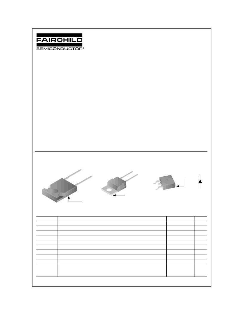
JEDEC TO-220AC
ANODE
CATHODE
JEDEC TO-263AB
CATHODE
(FLANGE)
N / C
2 LEAD TO-247
ANODE
CATHODE
CATHODE
(BOTTOM SIDE
METAL)
ANODE
CATHODE
(FLANGE)
Package
Symbol
相關PDF資料 |
PDF描述 |
|---|---|
| ISL9R30120G2 | 30A, 1200V Stealth⑩ Diode |
| ISL9R3060G2 | 30A, 600V Stealth⑩ Diode |
| ISL9R3060P2 | 30A, 600V Stealth⑩ Diode |
| ISL9R460S3S | 4A, 600V Stealth⑩ Diode |
| ISL9R460S3ST | 4A, 600V Stealth⑩ Diode |
相關代理商/技術參數(shù) |
參數(shù)描述 |
|---|---|
| ISL9R18120S3ST | 功能描述:整流器 18A 1200V Stealt RoHS:否 制造商:Vishay Semiconductors 產品:Standard Recovery Rectifiers 配置: 反向電壓:100 V 正向電壓下降: 恢復時間:1.2 us 正向連續(xù)電流:2 A 最大浪涌電流:35 A 反向電流 IR:5 uA 安裝風格:SMD/SMT 封裝 / 箱體:DO-221AC 封裝:Reel |
| ISL9R18120S3ST_Q | 功能描述:整流器 18A 1200V Stealt RoHS:否 制造商:Vishay Semiconductors 產品:Standard Recovery Rectifiers 配置: 反向電壓:100 V 正向電壓下降: 恢復時間:1.2 us 正向連續(xù)電流:2 A 最大浪涌電流:35 A 反向電流 IR:5 uA 安裝風格:SMD/SMT 封裝 / 箱體:DO-221AC 封裝:Reel |
| ISL9R2480G2 | 制造商:Rochester Electronics LLC 功能描述:- Bulk |
| ISL9R2480G2_S2611 | 制造商:Fairchild Semiconductor Corporation 功能描述: |
| ISL9R2480G2Q | 制造商:Fairchild Semiconductor Corporation 功能描述: |
發(fā)布緊急采購,3分鐘左右您將得到回復。