- 您現(xiàn)在的位置:買賣IC網(wǎng) > PDF目錄374335 > KH561AM (FAIRCHILD SEMICONDUCTOR CORP) Wideband, Low Distortion Driver Amplifier PDF資料下載
參數(shù)資料
| 型號(hào): | KH561AM |
| 廠商: | FAIRCHILD SEMICONDUCTOR CORP |
| 元件分類: | 運(yùn)動(dòng)控制電子 |
| 英文描述: | Wideband, Low Distortion Driver Amplifier |
| 中文描述: | OP-AMP, 5000 uV OFFSET-MAX, CDIP24 |
| 封裝: | CERAMIC, DIP-24 |
| 文件頁數(shù): | 3/13頁 |
| 文件大小: | 182K |
| 代理商: | KH561AM |

KH561
DATA SHEET
REV. 1A February 2001
3
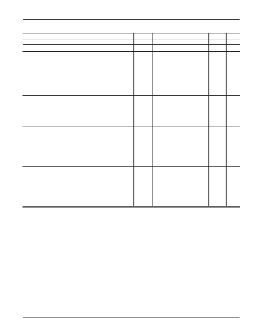
PARAMETERS
Case Temperature
Case Temperature
CONDITIONS
KH561AI
KH561AK/AM
TYP
+25
°
C
+25
°
C
MIN & MAX RATINGS
-25
°
C
+25
°
C
-55
°
C
+25
°
C
UNITS
SYM
+85
°
C
+125
°
C
TIME DOMAIN RESPONSE
(0% Overshoot Compensation)
rise and fall time
2V step
10V step
settling time to 0.5% (time <1
μ
s)
long term thermal tail (time >1
μ
s)
slew rate
overshoot
maximally flat compensation
0% overshoot compensation
EQUIVALENT INPUT NOISE
voltage
inverting current
non-inverting current
noise floor
integrated noise
noise figure
STATIC, DC PERFORMANCE
* input offset voltage
average temperature coefficient
* non-inverting bias current
average temperature coefficient
* inverting bias current
average temperature coefficient
* power supply rejection ratio (DC)
* supply current
MISCELLANEOUS PERFORMANCE
open loop current gain
average temperature coefficient
inverting input resistance
average temperature coefficient
non-inverting input resistance
non-inverting input capacitance
output voltage range
output current limit
1.5
2.4
7
1.5
3300
<2.0
<2.8
<12
<2.0
>3000
<1.9
<2.8
<12
<2.0
>2900
<2.0
<3.4
<15
<2.0
>2500
ns
ns
ns
%
V/
μ
s
TRS
TRL
TS
SE
SR
5V step
5V step
10V
pp
, 175MHz
2V step
5
0
<13
<5
<10
<3
<13
<5
%
%
OSMF
OSZO
>100KHz
>100KHz
>100KHz
>100KHz
1kHz to 200MHz
>100KHz
2.1
34
2.8
-159
35
15
<2.5
<40
<4.5
<-157
<45
<17 <17 <17
<2.5
<40
<4.5
<-157
<45 <45
<2.5
<45
<5.0
<-157
nV/
√
Hz
pA/
√
Hz
pA/
√
Hz
dBm/(1Hz)
μ
V
dB
VN
ICN
NCN
SNF
INV
NF
2.0
35
5.0
20
10.0
100
57
50
<14.0 <5.0 <15.0
<100
–
<35
<20
<175
–
<50
<30
<200
–
>54
>54
<60
<60
mV
μ
V/
°
C
μ
A
nA/
°
C
μ
A
nA/
°
C
dB
mA
VIO
DVIO
IBN
DIBN
IBI
DIBI
PSRR
ICC
<100
<20
<100
<50
<200
>52
<65
no load
(±2% tolerance)
10.0
+0.02
14.0
+.02
700
2.7
±10.5
210
–
–
–
–
–
–
mA/mA
%/
°
C
/
°
C
K
pF
V
mA
G
DG
RIN
DRIN
RNI
CNI
VO
OCL
<+.03
–
<+.025
>200
<3.5
–
<250
<+.02
–
<+.025
>400
<3.5
–
<250
(±5% tolerance)
>400
<3.5
>±10.0
<250
to 100MHz
150mA load current
Min/max ratings are based on product characterization and simulation. Individual parameters are tested as noted. Outgoing quality levels are
determined from tested parameters.
Absolute Maximum Ratings
V
CC
(reversed supplies will destroy part)
differential input voltage
common mode input voltage
junction temperature (see thermal model)
storage temperature
lead temperature (soldering 10s)
output current (internally limited)
Recommended Operating Conditions
V
CC
I
o
common mode input voltage
output impedance
gain range (no-load voltage gain)
case temperature: AI
AK/AM
±20V
±3V
±V
CC
+175
°
C
±10V to ±15V
≤
±200mA
< ±(|V
CC
| -6)V
25
to 200
+5 to +80
-25
°
C to +85
°
C
-55
°
C to +125
°
C
-65
°
C to +150
°
C
+300
°
C
±250mA
Notes
1) *
AI, AK, AM 100% tested at +25
°
C
AK, AM
100% tested at at +25
°
C and sample tested
at -55
°
C and +125
°
C
AI
sample tested at +25
°
C
2) Test Tones are set ±100kHz of indicated frequency.
KH561 Electrical Characteristics
(A
v
= +10V, V
CC
= ±15V, R
L
= 50
, R
f
= 410
, R
g
= 40
, R
o
= 50
; unless specified)
相關(guān)PDF資料 |
PDF描述 |
|---|---|
| KHB2442A01 | DIELECTRIC BAND PASS FILTER (TYPICAL PASSBAND CHARACTERISTIC) |
| KHB2450A01 | DIELECTRIC BAND PASS FILTER (TYPICAL PASSBAND CHARACTERISTIC) |
| KHR1060A01 | DIELECTRIC RESONATOR (FEATURES) |
| KHR0975A01 | TV 39C 37#20 2#16 PIN WALL REC |
| KHR1130A01 | DIELECTRIC RESONATOR (FEATURES) |
相關(guān)代理商/技術(shù)參數(shù) |
參數(shù)描述 |
|---|---|
| KH563 | 制造商:CADEKA 制造商全稱:CADEKA 功能描述:Wideband, Low Distortion Driver Amplifier |
| KH563AI | 功能描述:運(yùn)算放大器 - 運(yùn)放 DRIVER AMP 150MHz LOW DISTORTION RoHS:否 制造商:STMicroelectronics 通道數(shù)量:4 共模抑制比(最小值):63 dB 輸入補(bǔ)償電壓:1 mV 輸入偏流(最大值):10 pA 工作電源電壓:2.7 V to 5.5 V 安裝風(fēng)格:SMD/SMT 封裝 / 箱體:QFN-16 轉(zhuǎn)換速度:0.89 V/us 關(guān)閉:No 輸出電流:55 mA 最大工作溫度:+ 125 C 封裝:Reel |
| KH56921 | 制造商:P&B 功能描述:RELAY NOTE: Threaded Terminal is bent. |
| KH-5692-1 | 制造商:P&B 功能描述:RELAY NOTE: Threaded Terminal is bent. 制造商:TE Connectivity 功能描述:KH-5692-1=KH |
| KH56JM2-901 | 制造商:未知廠家 制造商全稱:未知廠家 功能描述:KH56QM2-951 |
發(fā)布緊急采購,3分鐘左右您將得到回復(fù)。