- 您現(xiàn)在的位置:買賣IC網(wǎng) > PDF目錄384586 > L6997 (意法半導(dǎo)體) STEP DOWN CONTROLLER FOR LOW VOLTAGE OPERATIONS PDF資料下載
參數(shù)資料
| 型號(hào): | L6997 |
| 廠商: | 意法半導(dǎo)體 |
| 英文描述: | STEP DOWN CONTROLLER FOR LOW VOLTAGE OPERATIONS |
| 中文描述: | 降壓控制器低電壓運(yùn)作 |
| 文件頁數(shù): | 9/23頁 |
| 文件大小: | 291K |
| 代理商: | L6997 |
9/23
L6997
ductor value is, the smaller the threshold is. On the other hand, the bigger the inductor value is, the slower the
transient response is. In PFM mode the frequency changes, with the output current changing, more than in
PWM mode; in fact if the output current increase, the output voltage decreases more quickly; so the successive
turn-on arrives before, increasing the switching frequency. The PFM waveforms may appear more noisy and
asynchronous than normal operation, but this is normal behaviour mainly due to the very low load. If the PFM
is not compatible with the application it can be disabled connecting to V
CC
the NOSKIP pin.
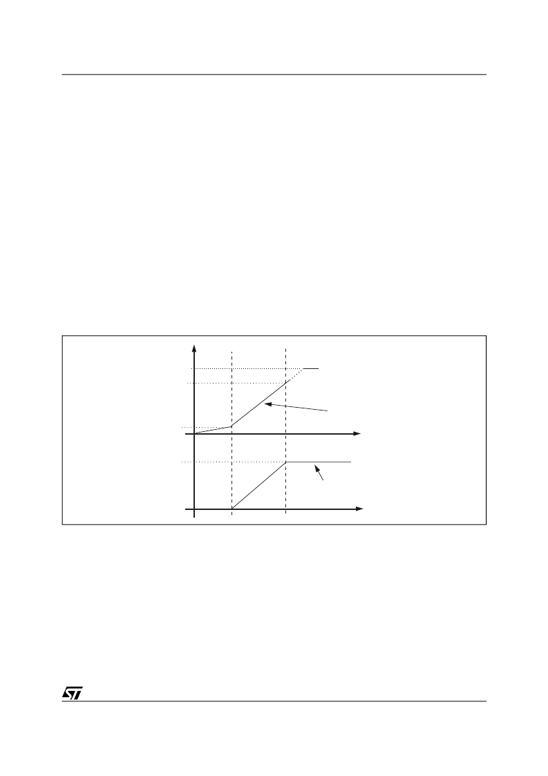
1.4 Softstart
If the supply voltages are already applied, the SHDN pin gives the start-up. The system starts with the high side
MOSFET and the low side MOSFET off (high impedance mode). After the SHDN pin is turned on the SS pin
voltage begins to increase and the system starts to switch. The softstart is realized by gradually increasing the
current limit threshold to avoid output overvoltage. The active soft start range for the V
SS
voltage (where the
output current limit increase linearly) starts from 0.6V to 1V. In this range an internal current source (5
μ
A Typ)
charges the capacitor on the SS pin; the reference current (for the current limit comparator) forced through ILIM
pin is proportional to SS pin voltage and it saturates at 5
μ
A (Typ.) when SS voltage is close to 1V and the max-
imum current limit is active. Output protections OVP & UVP are disabled until the SS pin voltage reaches 1V
(see figure 5).
Once the SS pin voltage reaches the 1V value, the voltage on SS pin doesn't impact the system operation any-
more. If the SHDN pin is turned on before the supplies, the correct start-up sequence is the following: first turn-
on the power section and after the logic section (V
CC
pin).
Figure 5. Soft -Start Diagram
Because the system implements the soft start controlling the inductor current, the soft start capacitor selection
is function of the output capacitance, the current limit and the soft start active range (
V
SS
).
In order to select the softstart capacitor it must be imposed that the output voltage reaches the final value before
the soft start voltage reaches the under voltage value (1V). In other words the output voltage charging time has
to be lower than the uvp time.
The UVP time is given by:
Eq 7
In order to calculate the output volatge chargin time it should be calculated, before, the output volatrge function
versus time. This function can be calculated from the inductor current function; the inductor current function can
Time
Time
0.6V
Maximum current limit
Soft-start active range
5
μ
A
4.1V
1V
Ilim current
Vss
T
uvp
C
SS
(
)
V
Iss
------------
C
SS
=
相關(guān)PDF資料 |
PDF描述 |
|---|---|
| L6997D | STEP DOWN CONTROLLER FOR LOW VOLTAGE OPERATIONS |
| L6997DTR | STEP DOWN CONTROLLER FOR LOW VOLTAGE OPERATIONS |
| L702 | 2A Quad Darlington Switches(2A四通道達(dá)林頓開關(guān)) |
| L70S70 | 16 Characters x 2 Lines, 5x7 Dot Matrix Character and Cursor |
| L70S20 | 16 Characters x 2 Lines, 5x7 Dot Matrix Character and Cursor |
相關(guān)代理商/技術(shù)參數(shù) |
參數(shù)描述 |
|---|---|
| L6997-28 | 制造商:Johanson Manufacturing 功能描述:TUNING ELEMENT |
| L6997-5 | 制造商:Johanson Manufacturing 功能描述:TUNING ELEMENT; Accessory Type:Tuning Element; For Use With:High Quality Variable Reactance Tuning Microwave Cavities, Filters & other Resonant Structures |
| L6997-9 | 制造商:Johanson Manufacturing 功能描述:TUNING ELEMENT |
| L6997D | 功能描述:DC/DC 開關(guān)控制器 Adjustable Step-Down RoHS:否 制造商:Texas Instruments 輸入電壓:6 V to 100 V 開關(guān)頻率: 輸出電壓:1.215 V to 80 V 輸出電流:3.5 A 輸出端數(shù)量:1 最大工作溫度:+ 125 C 安裝風(fēng)格: 封裝 / 箱體:CPAK |
| L6997DTR | 功能描述:DC/DC 開關(guān)控制器 Adjustable Step-Down RoHS:否 制造商:Texas Instruments 輸入電壓:6 V to 100 V 開關(guān)頻率: 輸出電壓:1.215 V to 80 V 輸出電流:3.5 A 輸出端數(shù)量:1 最大工作溫度:+ 125 C 安裝風(fēng)格: 封裝 / 箱體:CPAK |
發(fā)布緊急采購,3分鐘左右您將得到回復(fù)。