- 您現(xiàn)在的位置:買賣IC網(wǎng) > PDF目錄65953 > PLP-600+ (MINI-CIRCUITS) 640 MHz, LOW PASS FILTER PDF資料下載
參數(shù)資料
| 型號: | PLP-600+ |
| 廠商: | MINI-CIRCUITS |
| 英文描述: | 640 MHz, LOW PASS FILTER |
| 封裝: | ROHS COMPLIANT,HERMETIC SEALED, CASE A01, 8 PIN |
| 文件頁數(shù): | 1/1頁 |
| 文件大小: | 142K |
| 代理商: | PLP-600+ |
ISO 9001 ISO 14001 AS 9100 CERTIFIED
Mini-Circuits
P.O. Box 350166, Brooklyn, New York 11235-0003 (718) 934-4500 Fax (718) 332-4661 The Design Engineers Search Engine
Provides ACTUAL Data Instantly at
Notes: 1. Performance and quality attributes and conditions not expressly stated in this specification sheet are intended to be excluded and do not form a part of this specification sheet. 2. Electrical specifications
and performance data contained herein are based on Mini-Circuit’s applicable established test performance criteria and measurement instructions. 3. The parts covered by this specification sheet are subject to
Mini-Circuits standard limited warranty and terms and conditions (collectively, “Standard Terms”); Purchasers of this part are entitled to the rights and benefits contained therein. For a full statement of the Standard
Terms and the exclusive rights and remedies thereunder, please visit Mini-Circuits’ website at www.minicircuits.com/MCLStore/terms.jsp.
For detailed performance specs
& shopping online see web site
minicircuits.com
IF/RF MICROWAVE COMPONENTS
Maximum Ratings
Typical Performance Data
Frequency
(MHz)
Insertion Loss
(dB)
Low Pass Filter Electrical Specications
Operating Temperature
-55°C to 100°C
Storage Temperature
-55°C to 100°C
RF Power Input
0.5W max.
Return Loss
(dB)
Frequency
(MHz)
Group Delay
(nsec)
_
x
σ
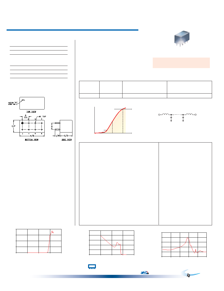
Low Pass Filter
PLP-600+
PLP-600
REV. A
M98898
PLP-600
090820
50
DC to 580 MHz
PASSBAND
(MHz)
fco (MHz)
Nom.
STOPBAND
(MHz)
VSWR
(:1)
(loss < 1 dB)
(loss 3 dB)
(loss > 20 dB)
(loss > 40 dB)
Passband
Typ.
Stopband
Typ.
DC-580
640
840-1120
1120-2000
1.7
18
electrical schematic
INSERTION LOSS
0
20
40
60
80
1
10
100
1000
10000
FREQUENCY(MHz)
INSERTION
LOSS
(dB)
at RF level of 0 dBm
RETURN LOSS
0
10
20
30
40
50
1
10
100
1000
10000
FREQUENCY(MHz)
R
E
TU
R
N
LO
S
(d
B
)
at RF level of 0 dBm
GROUP DELAY
0.0
1.0
2.0
3.0
4.0
5.0
0
220
440
660
880
1100
FREQUENCY (MHz)
G
R
O
U
P
D
E
LA
Y
(n
se
c)
at RF level of 0 dBm
typical frequency response
10.00
0.01
0.1
39.3
10.00
1.41
152.50
0.22
0.2
16.2
80.00
1.44
295.00
0.20
0.1
25.3
152.50
1.38
437.50
0.28
0.1
20.5
222.50
1.42
507.50
0.37
0.1
21.9
295.00
1.59
577.50
0.59
0.1
22.0
365.00
1.79
580.00
0.60
0.1
21.9
437.50
1.95
620.00
1.50
0.3
9.6
507.50
2.27
640.00
2.98
0.4
5.1
577.50
2.86
670.00
7.09
0.6
2.1
580.00
2.85
720.00
15.52
2.0
0.4
600.00
3.36
800.00
28.44
4.7
0.3
620.00
3.84
820.00
31.52
5.4
0.3
630.00
3.98
830.00
33.06
5.7
0.3
640.00
3.81
840.00
34.63
6.1
0.3
670.00
3.37
880.00
41.22
8.0
0.2
700.00
2.26
920.00
48.84
9.9
0.2
720.00
2.30
960.00
58.62
9.9
0.2
750.00
1.48
1000.00
59.95
9.9
0.2
800.00
0.77
1100.00
59.89
8.4
0.1
820.00
0.93
1120.00
62.05
8.8
0.1
830.00
1.54
1360.00
71.05
2.3
0.1
840.00
1.00
1502.50
73.53
9.3
0.2
880.00
0.79
1572.50
70.71
4.9
0.1
900.00
1.01
1650.00
67.12
3.4
0.1
920.00
1.11
1750.00
67.73
7.7
0.1
940.00
1.28
1800.00
70.74
9.5
0.1
960.00
1.15
1850.00
68.64
9.1
0.1
1000.00
1.02
1950.00
68.21
7.1
0.1
1100.00
0.95
2000.00
65.82
4.6
0.1
1120.00
0.85
Plug-In
CASE STYLE: A01
PRICE: $13.70 ea. QTY (1-9)
+ RoHS compliant in accordance
with EU Directive (2002/95/EC)
The +Sufx identies RoHS Compliance. See our web site
for RoHS Compliance methodologies and qualications.
Pin Connections
INPUT
1
OUTPUT
8
GROUND
2,3,4,5,6,7
CASE GROUND
2,3,4,5,6,7
Applications
test equipment
lab use
transmitters/receivers
military/hi-rel applications
Features
rugged welded case, hermetic
other standard and custom PLP models available with
wide selection of fco
inch
mm
Outline Drawing
Outline Dimensions (
)
R F IN
R F OUT
40 dB
20 dB
3 dB
1 dB
F R E QUE NC Y / F co
A
T
E
N
U
A
T
IO
N
,
d
B
DC
0.9
1
1.35
1.75
3
A
B
C
D
E
F
.770
.800
.385
.400
.370
.400
19.56 20.32
9.78 10.16
9.40 10.16
G
H
J
K
wt
.200
.20
.14
.031
grams
5.08
3.56
0.79
5.2
Permanent damage may occur if any of these limits are exceeded.
相關PDF資料 |
PDF描述 |
|---|---|
| PLP-7-75+ | 8 MHz, LOW PASS FILTER |
| PLP-70-75+ | 67 MHz, LOW PASS FILTER |
| PLP-750+ | 770 MHz, LOW PASS FILTER |
| PLP-750 | 770 MHz, LOW PASS FILTER |
| PLP-850-75+ | 850 MHz, LOW PASS FILTER |
相關代理商/技術參數(shù) |
參數(shù)描述 |
|---|---|
| PLP60-1005 | 制造商:Power-One 功能描述:- Bulk |
| PLP60-1012 | 制造商:Power-One 功能描述:- Bulk |
| PLP60-1024 | 制造商:Power-One 功能描述:- Bulk |
| PLP-60-12 | 功能描述:LED電源 60W 12V 5A LED Power Supply RoHS:否 制造商:Cree, Inc. 工作模式:Constant Voltage (CV) 輸出功率額定值: 輸入電壓:220 V to 240 V 輸出端數(shù)量:1 輸出電壓(通道 1):40 V 輸出電流(通道 1):900 mA 安裝風格:Screw 尺寸:90 mm L x 90 mm W x 37.5 mm H 商用/醫(yī)用:Commercial |
| PLP-60-24 | 功能描述:LED電源 60W 24V 2.5A LED Power Supply RoHS:否 制造商:Cree, Inc. 工作模式:Constant Voltage (CV) 輸出功率額定值: 輸入電壓:220 V to 240 V 輸出端數(shù)量:1 輸出電壓(通道 1):40 V 輸出電流(通道 1):900 mA 安裝風格:Screw 尺寸:90 mm L x 90 mm W x 37.5 mm H 商用/醫(yī)用:Commercial |
發(fā)布緊急采購,3分鐘左右您將得到回復。