- 您現(xiàn)在的位置:買賣IC網(wǎng) > PDF目錄299803 > QT71HCD9M-50.000MHZ (Q-TECH CORP) CRYSTAL OSCILLATOR, CLOCK, 50 MHz, HCMOS OUTPUT PDF資料下載
參數(shù)資料
| 型號: | QT71HCD9M-50.000MHZ |
| 廠商: | Q-TECH CORP |
| 元件分類: | XO, clock |
| 英文描述: | CRYSTAL OSCILLATOR, CLOCK, 50 MHz, HCMOS OUTPUT |
| 封裝: | ROHS COMPLIANT, LEADLESS, CERAMIC, SMD, 28 PIN |
| 文件頁數(shù): | 5/6頁 |
| 文件大小: | 485K |
| 代理商: | QT71HCD9M-50.000MHZ |
5
Q-TECH Corporation - 10150 W. Jefferson Boulevard, Culver City 90232 - Tel: 310-836-7900 - Fax: 310-836-2157 - www.q-tech.com
LEADLESS CHIP CARRIER
CRYSTAL CLOCK OSCILLATORS
1.8 to 15Vdc - 732.4Hz to 150MHz
Q-TECH
CORPORATION
Leadless Chip Carrier (Revision G, August 2010) (ECO# 9935)
45
Hybrid Case
Substrate
Die
D/A epoxy
Heat
Die
R1
D/A epoxy
Substrate
D/A epoxy
Hybrid Case
R2
R3
R4
R5
Thermal Characteristics
JA
JC
CA
Die
T
C
A
J
CA
JC
(Figure 1)
(Figure 2)
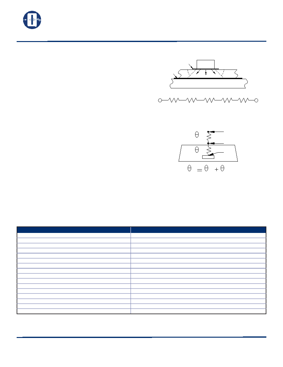
The heat transfer model in a hybrid package is described in
figure 1.
Heat spreading occurs when heat flows into a material layer of
increased cross-sectional area. It is adequate to assume that
spreading occurs at a 45° angle.
The total thermal resistance is calculated by summing the
thermal resistances of each material in the thermal path
between the device and hybrid case.
RT = R1 + R2 + R3 + R4 + R5
The total thermal resistance RT (see figure 2) between the heat
source (die) to the hybrid case is the Theta Junction to Case
(Theta JC) in°C/W.
Theta junction to case (Theta JC) for this product is 30°C/W.
Theta case to ambient (Theta CA) for this part is 100°C/W.
Theta Junction to ambient (Theta JA) is 130°C/W.
Maximum power dissipation PD for this package at 25°C is:
PD(max) = (TJ (max) – TA)/Theta JA
With TJ = 175°C (Maximum junction temperature of die)
PD(max) = (175 – 25)/130 = 1.15W
Environmental Specifications
Q-Tech Standard Screening/QCI (MIL-PRF55310) is available for all of our Leadless Chip Carrier packages. Q-Tech can also
customize screening and test procedures to meet your specific requirements. The Leadless Chip Carrier packages are designed and
processed to exceed the following test conditions:
Environmental Test
Test Conditions
Temperature cycling
MIL-STD-883, Method 1010, Cond. B
Constant acceleration
MIL-STD-883, Method 2001, Cond. A, Y1
Seal: Fine and Gross Leak
MIL-STD-883, Method 1014, Cond. A and C
Burn-in
160 hours, 125°C with load
Aging
30 days, 70°C, ± 1.5ppm max
Vibration sinusoidal
MIL-STD-202, Method 204, Cond. D
Shock, non operating
MIL-STD-202, Method 213, Cond. I
Thermal shock, non operating
MIL-STD-202, Method 107, Cond. B
Ambient pressure, non operating
MIL-STD-202, 105, Cond. C, 5 minutes dwell time minimum
Resistance to solder heat
MIL-STD-202, Method 210, Cond. B
Moisture resistance
MIL-STD-202, Method 106
Terminal strength
MIL-STD-202, Method 211, Cond. C
Resistance to solvents
MIL-STD-202, Method 215
Solderability
MIL-STD-202, Method 208
ESD Classification
MIL-STD-883, Method 3015, Class 1HBM 0 to 1,999V
Moisture Sensitivity Level
J-STD-020, MSL=1
Please contact Q-Tech for higher shock requirements
相關(guān)PDF資料 |
PDF描述 |
|---|---|
| QTE-020-01-L-D-LC | 40 CONTACT(S), MALE, STRAIGHT BOARD STACKING CONNECTOR, SURFACE MOUNT |
| QTE-020-03-H-D-A | 40 CONTACT(S), MALE, STRAIGHT BOARD STACKING CONNECTOR, SURFACE MOUNT |
| QTE-020-03-L-D-K | 40 CONTACT(S), MALE, STRAIGHT BOARD STACKING CONNECTOR, SURFACE MOUNT |
| QTE-020-03-L-D-LC | 40 CONTACT(S), MALE, STRAIGHT BOARD STACKING CONNECTOR, SURFACE MOUNT |
| QTE-020-04-H-D-A | 40 CONTACT(S), MALE, STRAIGHT BOARD STACKING CONNECTOR, SURFACE MOUNT |
相關(guān)代理商/技術(shù)參數(shù) |
參數(shù)描述 |
|---|---|
| QT7F | 制造商:Switchcraft 功能描述:QG TWIST INSERT 7 P |
| QT7FBAU | 制造商:Switchcraft 功能描述:QG TWIST INSERT BLA |
| QT7M | 制造商:Switchcraft 功能描述:QG TWIST INSERT 7 P |
| QT7MB | 制造商:Switchcraft 功能描述:QG TWIST INSERT 7 PI |
| QT7MBAU | 制造商:Switchcraft 功能描述:QG TWIST INSERT BLA |
發(fā)布緊急采購,3分鐘左右您將得到回復(fù)。