- 您現(xiàn)在的位置:買賣IC網 > PDF目錄23052 > 0451.500MR SICHERUNG SMD 500MA 10ST PDF資料下載
參數(shù)資料
| 型號: | 0451.500MR |
| 英文描述: | SICHERUNG SMD 500MA 10ST |
| 中文描述: | SICHERUNG貼片500mA的10ST |
| 文件頁數(shù): | 1/1頁 |
| 文件大小: | 138K |
| 代理商: | 0451.500MR |
34
SURFACE MOUNT FUSES
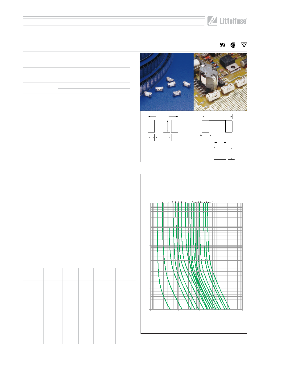
SUBMINIATURE SURFACE MOUNT
NANO
2 SMF Very Fast-Acting Type Fuse
The Nano2 SMF Fuse is a very small, square surface mount
fuse that is also available in a surface mount holder.
ELECTRICAL CHARACTERISTICS:
% of Ampere
Ampere
Opening
Rating
Time
100%
1/16 –15
4 hours, Minimum
200%
1/16 –10
5 seconds, Maximum
12–15
20 seconds, Maximum
AGENCY APPROVALS: Recognized under the Components
Program of Underwriters Laboratories and Certified by
CSA. Approved by MITI from 1 through 5 amperes.
AGENCY FILE NUMBERS: UL E10480, CSA LR 29862.
INTERRUPTING RATINGS:
1/16 – 8A
50 amperes at 125 VAC/VDC
300 amperes at 32 VDC
10A
35 amperes at 125 VAC/50 amperes at 125 VDC
300 amperes at 32 VDC
12A – 15A 50 amperes at 65 VAC/VDC
300 amperes at 24 VDC
ENVIRONMENTAL SPECIFICATIONS:
Operating Temperature: –55°C to 125°C.
Shock: MIL-STD-202, Method 213, Test Condition I (100
G’s peak for 6 milliseconds).
Vibration: MIL-STD-202, Method 201 (10–55 Hz).
Salt Spray: MIL-STD-202, Method 101, Test Condition B.
Insulation Resistance (After Opening): MIL-STD-202,
Method 302, Test Condition A, (10,000 ohms minimum).
Resistance to Soldering Heat: MIL-STD-202,
Method 210, Test Condition F (20 sec. at 260°C).
Thermal Shock: MIL-STD-202, Method 107,
Test Condition B (–65 to 125°C).
Moisture Resistance: MIL-STD-202, Method 106, High
Humidity (90-98 RH), Heat (65°C).
PHYSICAL SPECIFICATIONS:
Materials: Body: Ceramic
Terminations: Tin-Lead Alloy or Silver
Plated Brass Caps.
Soldering Parameters:
Wave Solder — 260°C, 10 seconds maximum
Reflow Solder — 260°C, 30 seconds maximum
Solderability: MIL-STD-202, Method 208.
PACKAGING SPECIFICATIONS: 12mm Tape and Reel
per EIA-RS481 (IEC 286, part 3); 1,000 per reel, add
packaging suffix, MR.
PATENTED
ORDERING INFORMATION:
100
10
1
0.1
0.01
0.001
1/16A
1/8A
1/4A
3/8A
1/2A 3/4A
1A
1
1/2A
2A 2
1/2A
3A 3
1/2A
4A
5A 7A
10A 12A 15A
0.05 0.1
1
10
100
1000
TIME
IN
SECONDS
CURRENT IN AMPERES
Refer to pg. 102 for SMF Omni-Blok Holder, Series 154 000.
Average Time Current Curves
LF
7 A
6.86
(.270")
3.15
(.124")
2.95
(.116")
1.96
(.077")
2.69
(.106")
2.69
(.106")
1.45
(.057")
6.10
(.240")
Note: Metric dimensions shown.
Inch dimensions are in parentheses.
Recommended pad layout
Tin-Lead
Silver
Nominal
Plated
Ampere Voltage Resistance
Melting I
2t
Catalog #
Rating
Rating Cold Ohms
A
2 Sec.
–
R451.062
1/16
125
5.50
0.00019
–
R451.125
1/8
125
1.70
0.00286
R451.250
0453.250
1/4
125
1.05
0.01126
R451.375
0453.375
3/8
125
0.610
0.0425
R451.500
0453.500
1/2
125
0.420
0.0795
R451.750
0453.750
3/4
125
0.245
0.185
R451 001.
0453 001.
1
125
0.153
0.459
R451 01.5
0453 01.5
11/2
125
0.0630
0.853
R451 002.
0453 002.
2
125
0.0367
0.53
R451 02.5
0453 02.5
21/2
125
0.0286
1.029
R451 003.
0453 003.
3
125
0.0227
1.65
R451 03.5
0453 03.5
31/2
125
0.0200
2.469
R451 004.
0453 004.
4
125
0.0160
3.152
R451 005.
0453 005.
5
125
0.0125
5.566
R451 007.
0453 007.
7
125
0.0090
10.32
R451 010.
0453 010.
10
125
0.0056
26.46
R451 012.
0453 012.
12
65
0.0049
47.97
R451 015.
0453 015.
15
65
0.0037
97.82
相關PDF資料 |
PDF描述 |
|---|---|
| 0451001.MR | SICHERUNG SMD 1A 10ST |
| 0451002.MR | SICHERUNG SMD 2A 10ST |
| 0451003.MR | SC70/µDFN, Single/Dual Low-Voltage, Low-Power µP Reset Circuits |
| 0451005.MR | SC70/µDFN, Single/Dual Low-Voltage, Low-Power µP Reset Circuits |
| 09211.111.071 | 2.5 mm2, COPPER ALLOY, RING TERMINAL |
相關代理商/技術參數(shù) |
參數(shù)描述 |
|---|---|
| 0451560100 | 制造商:Molex 功能描述:.156" DOUBLE END CABLE ASSY. - Bulk |
| 0451560215 | 制造商:Molex 功能描述:.156 DOUBLE END CABLE ASSY. 451560215IN - Bulk |
| 045159-0000 | 制造商:ITT Interconnect Solutions 功能描述:045159-0000 - Bulk |
| 045160-0000 | 制造商:ITT Interconnect Solutions 功能描述:C/C ADAPTR-14/14S 045160-0000 - Bulk |
| 045161-0000 | 制造商:ITT Interconnect Solutions 功能描述:C/C ADAPTR-16/16S 045161-0000 - Bulk |
發(fā)布緊急采購,3分鐘左右您將得到回復。