- 您現(xiàn)在的位置:買賣IC網(wǎng) > PDF目錄22730 > 08-M164-KIT-FEC IMPACT PRINTER KIT PDF資料下載
參數(shù)資料
| 型號(hào): | 08-M164-KIT-FEC |
| 英文描述: | IMPACT PRINTER KIT |
| 中文描述: | 撞擊式印表機(jī)盒 |
| 文件頁(yè)數(shù): | 9/11頁(yè) |
| 文件大小: | 96K |
| 代理商: | 08-M164-KIT-FEC |
5.4 Busy Output Signal
The controller asserts the Busy output when the input buffer is one character away from being full. The
following character will, however, be loaded into the input buffer. This avoids any data being lost due to
the host not responding to the busy signal immediately (such as with a double-buffered UART in a PC).
5.5 Printing modes and data buffer
Character printing modes include graphics, inverted, double height and double width. Graphics mode is
cancelled at the end of every dot line, whereas the combinations of double height and width remain in
force until cancelled by a new command.
The A104B will print data before the ESCape code and then implement the new mode selection. The
data buffer accommodates 48 bytes, which can extend over many physical print lines, depending on the
mechanism in use and the data format; and new data can be entering the buffer as previous data are
being printed.
5.6 Character Printing
The A104B prints the characters from left to right. The characters fit into a 6 wide × 10 high matrix. The
standard letter is 5 wide × 7 high, this provides for a one dot space between each character, a dot line
for descenders and a dot line above and below each character line. The number of characters required
to fill a dot line varies according to the printer mechanism.
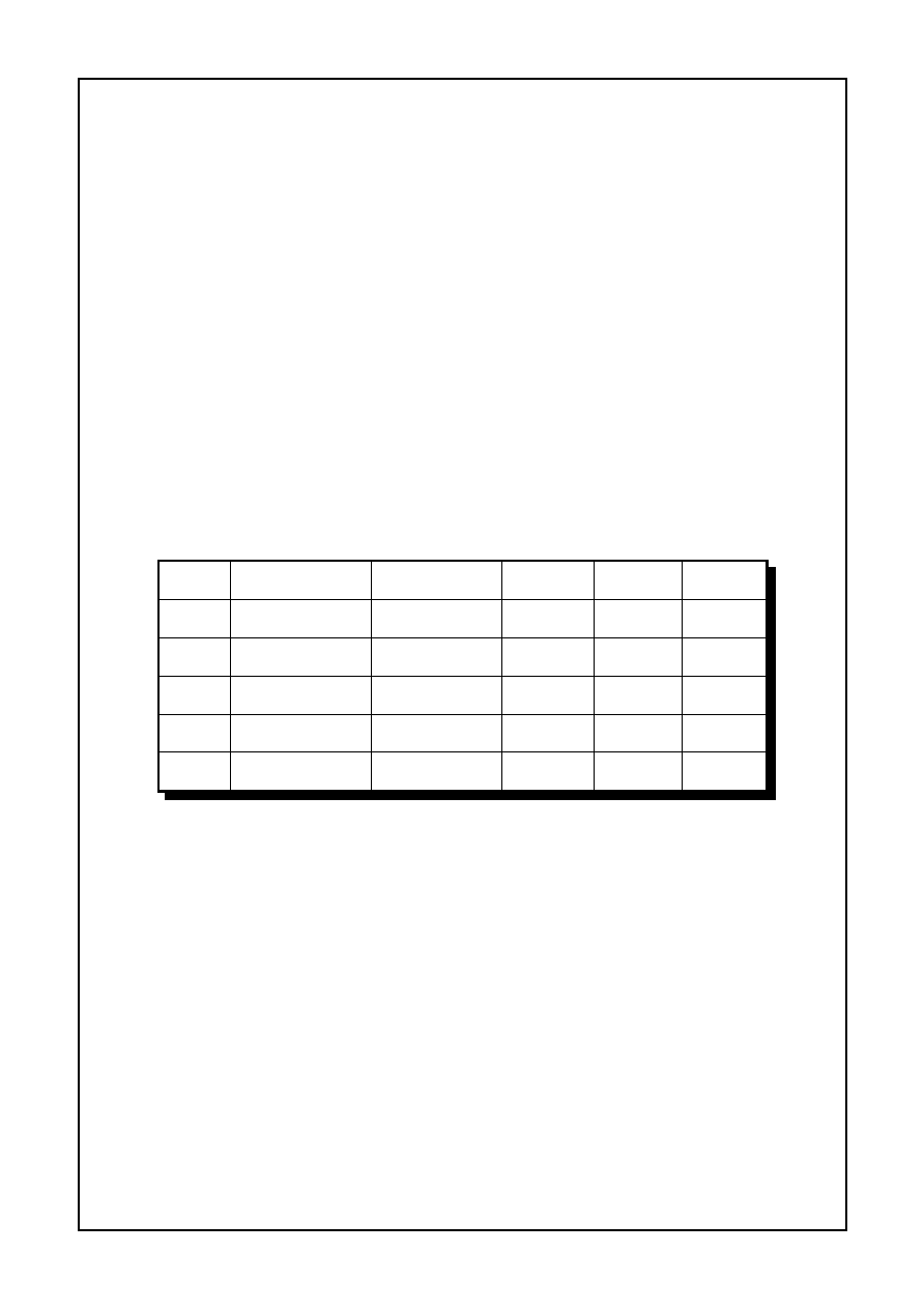
69.5mm
0.25mm
0.33mm
0.4 lines/second
40 characters per
line
M-170
57.5mm
0.20mm
0.33mm
0.4 lines/second
40 characters per
line
M-164
57.5mm
0.25mm
0.33mm
0.5 lines/second
32 characters per
line
M-163
57.5mm
0.33mm
0.7 lines/second
24 characters per
line
M-160
44.5mm
0.35mm
1 line/second
16 characters per
line
M-150
Paper
width
Horizontal
dot pitch
Vertical
dot pitch
Character lines
per second
Characters per
line
Mech.
The ASCII characters 32 to 255 (32 to 127 if using a backwards compatible 7 bit character set) are in
the printable range. Any character below character 32 is ignored unless it is one of the control codes
(section 5.8).
5.7 Graphics Printing
The product is programmed to take advantage of the graphics printing capability of the mechanisms.
Graphics are received as the least significant 6 bits of each byte. The same number of graphics bytes
are required to terminate a line as the number of characters required to print a complete line. The
graphics mode is reset at the end of every dot line and hence the graphics command, <ESC><02>,
must be entered at the start of every dot line. Graphics patterns are built up as a succession of dot
lines across the paper. Large areas of solid dots are not recommended as they may cause over heating
and shorten the ribbon life. Heavy graphics printing may also require a higher current power supply.
A typical graphics line for the A104B would be:
Control code
Data (24 bytes for the M-160 printer mechanism)
<ESC><02>
<00><00><01><02><03><04><05> etc.
A104B Users’ Guide Page 7 of 11
相關(guān)PDF資料 |
PDF描述 |
|---|---|
| 05247.122.003 | 10 mm2, BRASS, WIRE TERMINAL |
| 05247.122.011 | 10 mm2, BRASS, TIN FINISH, WIRE TERMINAL |
| 05247.122.014 | 10 mm2, BRASS, WIRE TERMINAL |
| 05243.123.003 | 12 mm2, BRASS, WIRE TERMINAL |
| 05245.122.014 | 12 mm2, BRASS, TIN FINISH, WIRE TERMINAL |
相關(guān)代理商/技術(shù)參數(shù) |
參數(shù)描述 |
|---|---|
| 08M2001FF | 制造商:VISHAY 制造商全稱:Vishay Siliconix 功能描述:NTC Thermistors,Coated |
| 08M2001FP | 制造商:VISHAY 制造商全稱:Vishay Siliconix 功能描述:NTC Thermistors,Coated |
| 08M2001JF | 制造商:VISHAY 制造商全稱:Vishay Siliconix 功能描述:NTC Thermistors,Coated |
| 08M2001JP | 制造商:VISHAY 制造商全稱:Vishay Siliconix 功能描述:NTC Thermistors,Coated |
| 08M2001KF | 制造商:VISHAY 制造商全稱:Vishay Siliconix 功能描述:NTC Thermistors,Coated |
發(fā)布緊急采購(gòu),3分鐘左右您將得到回復(fù)。