- 您現(xiàn)在的位置:買賣IC網(wǎng) > PDF目錄62838 > 1.5.2000-DV-230 1-OUTPUT AC-DC REG PWR SUPPLY MODULE PDF資料下載
參數(shù)資料
| 型號: | 1.5.2000-DV-230 |
| 元件分類: | 電源模塊 |
| 英文描述: | 1-OUTPUT AC-DC REG PWR SUPPLY MODULE |
| 文件頁數(shù): | 2/2頁 |
| 文件大小: | 65K |
| 代理商: | 1.5.2000-DV-230 |
)
D-
204
STCO
#970624-1,
STCO
#990908-1
PC Board Mountable Power Supplies
2
Manufacturing Company, Inc. Concord, California 94520 Ph: 925/687-4411 or 800/542-3355 Fax: 925/687-3333 www.calex.com Email: sales@calex.com
-30
-20
-10
0
10
20
30
40
50
60
70
80
CASE TEMPERATURE (Deg C)
0
20
40
60
80
100
120
MAXIMUM
OUTPUT
POWER
(%)
AC/DC POWER SUPPLY DERATING
s
n
o
i
t
c
e
n
o
C
t
i
K
g
n
i
t
n
u
o
M
o
t
e
s
a
C
n
i
P
e
s
a
C2
2
0
-
5
1
2
K
MV
D
B
8
0
-
5
1
2
K
M
A
1
,
1X
2
2-
-
3-
-
A
4
,
4Z
1
5K
6
6H
5
7E
7
8C
4
9A
8
.
e
s
a
c
e
h
t
n
i
d
e
t
r
e
s
n
i
t
o
n
e
r
a
d
e
c
n
e
r
e
f
e
r
t
o
n
s
n
i
P
s
t
n
e
m
n
g
i
s
A
n
i
P
n
i
Pn
o
i
t
c
n
u
F
9e
g
a
t
l
o
V
t
u
p
t
u
O
+
5e
g
a
t
l
o
V
t
u
p
t
u
O
-
7n
o
m
o
C
5
t
u
p
t
u
O
e
l
g
n
i
S
n
O
5
n
i
P
o
t
d
e
t
c
e
n
o
c
o
s
l
a
s
i
n
o
m
o
C
8t
u
p
t
u
O
V
5
s
t
i
n
U
e
l
p
i
r
T
n
O
6
n
o
m
o
C
V
5
s
t
i
n
U
e
l
p
i
r
T
n
O
m
o
r
f
d
e
t
a
l
o
s
I
(±
)
n
o
m
o
C
A
1
r
o
1
A
4
r
o
4
C
A
V
0
4
2
,
0
3
2
,
0
2
,
5
1
,
0
1
t
u
p
n
I
C
A
s
t
i
n
U
C
D
d
n
a
t
u
p
n
I
C
A
3
&
2
r
e
p
m
u
JV
0
3
2
-
s
t
i
n
U
V
D
3
o
t
1
r
e
p
m
u
J
4
o
t
2
&
V
5
1
-
s
t
i
n
U
V
D
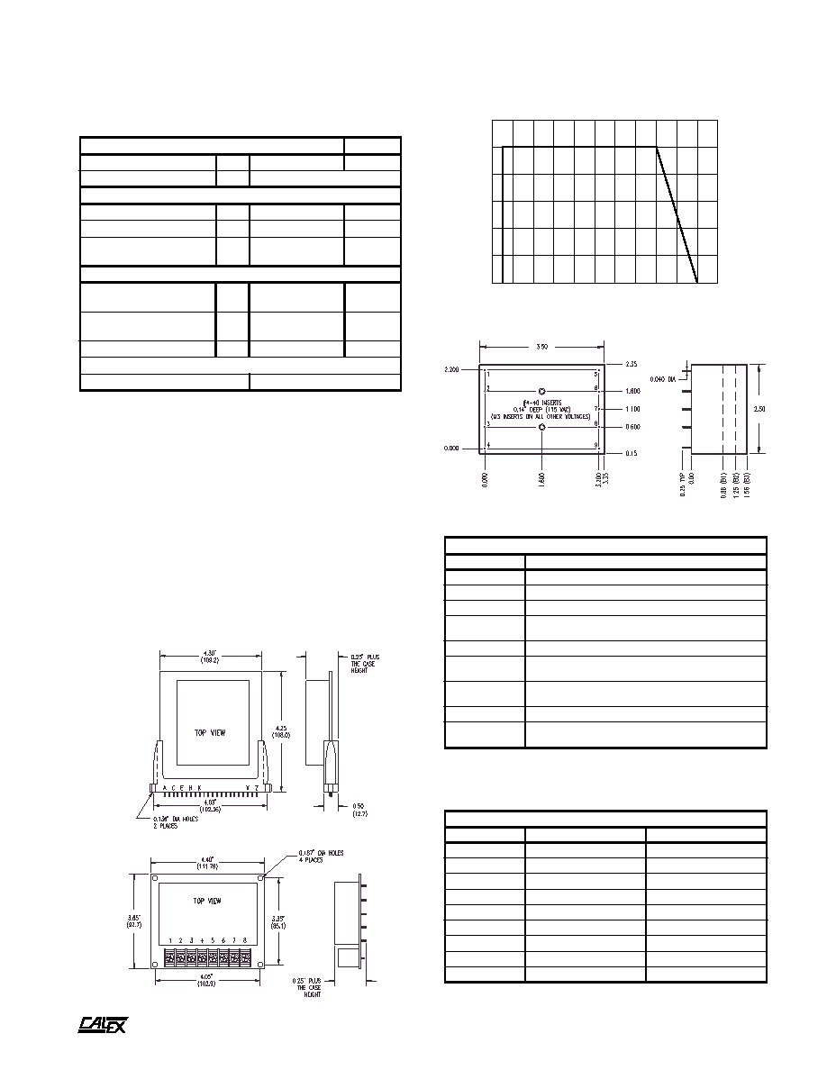
SAFE OPERATING
AREA
Specifications
All parameters measured at 25 C, nominal input voltage and full rated
load unless otherwise noted.
Single 5 Volt output models have output overvoltage protection
which operates between 5.8V and 6.85 Volts. Power must be
removed to reset the clamp.
Power Supply Mounting Kit Options
Two types of mounting kits are available for convenient
installation of CALEX power supplies. The MK215-022 consists
of a PC card with a 22-pin connector for use in racks. The
alternative, our MK215-08BDV, employs a barrier strip type
connector for chassis mount applications. Two screws hold
the power supply firmly in place on the PC card without need
of soldering.
MK215-022
MK215-08BDV
Mechanical tolerances unless otherwise noted:
X.XX dimensions: 0.020 inches
X.XXX dimensions: 0.005 inches
“A” models have 2" spacing between AC pins. (e.g. 2.15.200A)
Bottom View
Side View
B1, B2, B3 case
s
l
e
d
o
M
l
At
i
n
U
e
g
n
a
R
y
c
n
e
u
q
e
r
F
t
u
p
n
IP
Y
T0
6
o
t
0
5z
H
n
o
i
t
c
e
t
o
r
P
t
i
u
c
r
i
C
t
r
o
h
SP
Y
Tg
n
i
t
i
m
i
L
t
n
e
r
u
C
k
c
a
b
d
l
o
F
n
o
i
t
a
l
o
s
I
e
c
n
a
t
s
i
s
e
R
n
o
i
t
a
l
o
s
IN
I
M0
5m
h
o
g
e
m
*
e
g
a
t
l
o
V
n
o
i
t
a
l
o
s
IN
I
M0
0
5
1
-
0
2
1S
M
R
V
t
u
p
t
u
O
o
t
u
p
n
I
*
e
c
n
a
t
i
c
a
p
a
C
P
Y
T0
5
2
-
0
5F
p
l
a
t
n
e
m
n
o
r
i
v
n
E
e
g
n
a
R
g
n
i
t
a
r
e
p
O
e
s
a
C
g
n
i
t
a
r
e
D
o
N
I
M
X
A
M
5
2
-
0
5
+
C
°
e
g
n
a
R
e
g
a
r
o
t
S
N
I
M
X
A
M
5
2
-
5
8
+
C
°
t
n
e
i
c
i
f
e
o
C
e
r
u
t
a
r
e
p
m
e
TP
Y
T1
0
.
0
±C
°
/
%
e
s
a
C3
B
&
,
2
B
,
1
B
s
t
i
K
g
n
i
t
n
u
o
MV
D
B
8
0
-
5
1
2
K
M
&
2
0
-
5
1
2
K
M
ll
a
c
,
l
e
d
o
m
t
c
a
x
e
n
o
n
o
i
t
a
m
r
o
f
n
i
r
o
f
X
E
L
A
C
t
c
a
t
n
o
C
*
1
4
-
7
8
6
)
5
2
9
(
r
o
5
3
-
2
4
5
)
0
8
(
相關(guān)PDF資料 |
PDF描述 |
|---|---|
| 1.12.480-DV-230 | 1-OUTPUT AC-DC REG PWR SUPPLY MODULE |
| 1.5.2000-DV-115 | 1-OUTPUT AC-DC REG PWR SUPPLY MODULE |
| 1.12.480-DV-100 | 1-OUTPUT AC-DC REG PWR SUPPLY MODULE |
| 1.5.2000-DV-240 | 1-OUTPUT AC-DC REG PWR SUPPLY MODULE |
| 1.5.2000-DV-220 | 1-OUTPUT AC-DC REG PWR SUPPLY MODULE |
相關(guān)代理商/技術(shù)參數(shù) |
參數(shù)描述 |
|---|---|
| 152001 | 制造商:LITTELFUSE 制造商全稱:Littelfuse 功能描述:MAXI Fuse In-Line Fuseholder |
| 1520013 | 功能描述:電纜組件 SACC-E-MSB-5CON- M16/0,5 SCO RoHS:否 制造商:Molex 產(chǎn)品:Power Assemblies 類型:Cable Assembly 連接器端口 A:No Connector 連接器端口 A 管腳計數(shù):4 連接器端口 B:No Connector 連接器端口 B 管腳計數(shù): 型式:Male 線規(guī) - 美國線規(guī)(AWG):20, 28 長度:0.305 m 顏色:Black, Red |
| 152-001977-0001 | 制造商:Amphenol Aerospace 功能描述:FILTER CONNECTOR |
| 152-0024 | 制造商:Triplett Corporation 功能描述:test |
| 15200250 | 制造商:CML Innovative Technologies 功能描述:LED T10 BA9S 12VDC RED |
發(fā)布緊急采購,3分鐘左右您將得到回復(fù)。