- 您現(xiàn)在的位置:買賣IC網(wǎng) > PDF目錄368692 > 100331 (Fairchild Semiconductor Corporation) Low Power Triple D-Type Flip-Flop PDF資料下載
參數(shù)資料
| 型號: | 100331 |
| 廠商: | Fairchild Semiconductor Corporation |
| 英文描述: | Low Power Triple D-Type Flip-Flop |
| 中文描述: | 低功耗三D類觸發(fā)器 |
| 文件頁數(shù): | 4/8頁 |
| 文件大小: | 150K |
| 代理商: | 100331 |
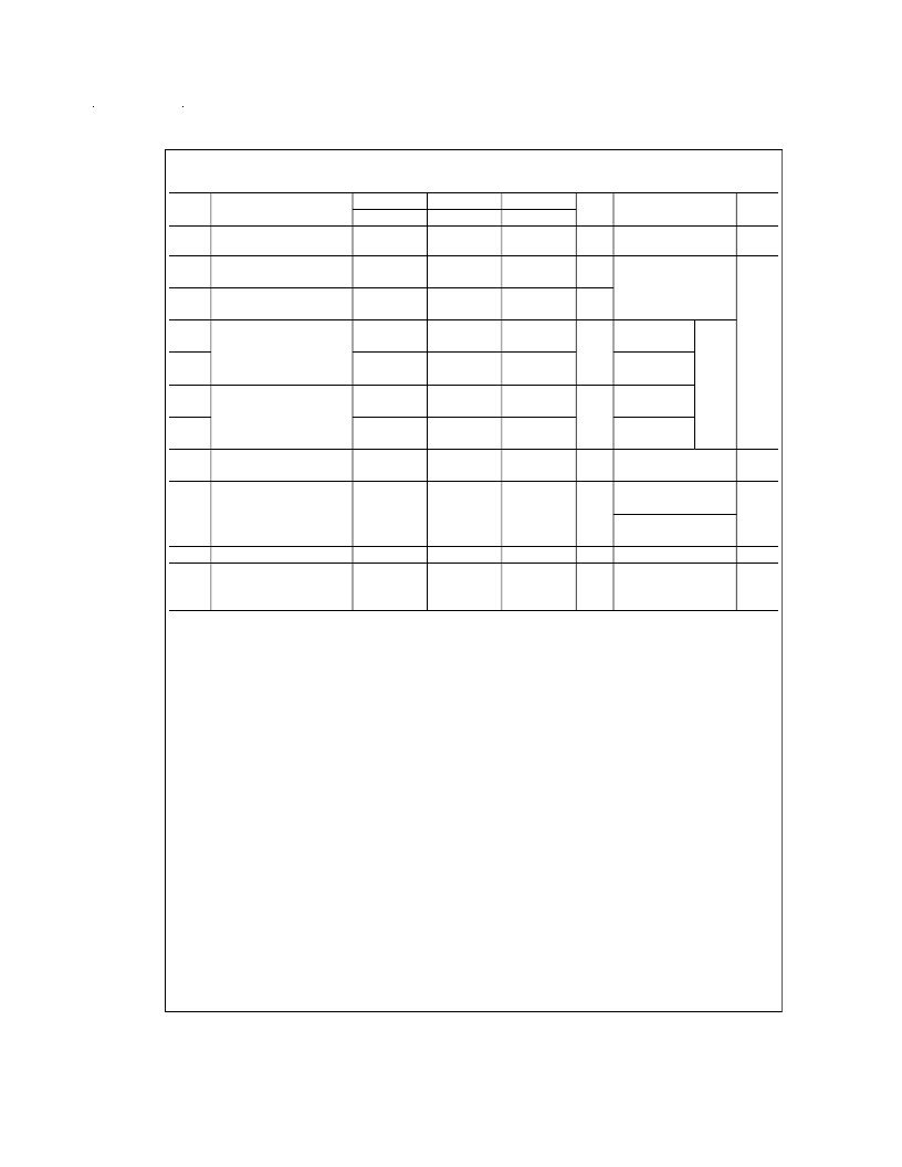
AC Electrical Characteristics
V
EE
= 4.2V to 5.7V, V
CC
= V
CCA
= GND
Symbol
Parameter
T
C
= 55C
Min
400
T
C
= +25C
Min
400
T
C
= +125C
Min
400
Units
Conditions
Notes
Max
Max
Max
f
max
Toggle Frequency
MHz
Figures 2, 3
(Note
10)
t
PLH
t
PHL
t
PLH
t
PHL
t
PLH
t
PHL
t
PLH
t
PHL
t
PLH
t
PHL
t
PLH
t
PHL
t
TLH
t
THL
t
s
Propagation Delay
CP
C
to Output
Propagation Delay
CP
n
to Output
Propagation Delay
CD
n
, SD
n
to Output
0.50
2.20
0.60
2.00
0.50
2.40
ns
Figures 1, 3
0.50
2.20
0.60
2.00
0.50
2.40
ns
0.50
2.20
0.60
2.00
0.50
2.40
CP
n
, CP
C
= L
Figures
1, 4
(Notes
7, 8,
9)
ns
0.50
2.40
0.60
2.10
0.50
2.50
CP
n
, CP
C
= H
Propagation Delay
MS, MR to Output
0.70
2.70
0.80
2.60
0.80
2.90
CP
n
, CP
C
= L
ns
0.70
2.90
0.80
2.80
0.80
3.10
CP
n
, CP
C
= H
Transition Time
20% to 80%, 80% to 20%
Setup Time
D
n
CD
n
, SD
n
(Release Time)
MS, MR (Release Time)
Hold Time D
n
Pulse Width HIGH
CP
n
, CP
C
, CD
n
,
SD
n
, MR, MS
0.20
1.40
0.20
1.40
0.20
1.40
ns
Figures 1, 3, 4
Figure 5
(Note
10)
1.00
1.50
2.50
1.50
0.80
1.30
2.30
1.30
0.90
1.60
2.50
1.60
ns
Figure 4
t
h
t
pw
(H)
ns
Figure 5
2.00
2.00
2.00
ns
Figures 3, 4
Note 7:
F100K 300 Series cold temperature testing is performed by temperature soaking (to guarantee junction temperature equals 55C), then testing immediately
without allowing for the junction temperature to stabilize due to heat dissipation after power-up. This provides “cold start” specs which can be considered a worst case
condition at cold temperatures.
Note 8:
Screen tested 100% on each device at +25C. Temperature only, Subgroup A9.
Note 9:
Sample tested (Method 5005, Table I) on each Mfg. lot at +25C, Subgroup A9, and at +125C, and 55C Temp., Subgroups A10 and A11.
Note 10:
Not tested at +25C, +125C and 55C Temperature (design characterization data).
www.national.com
4
相關(guān)PDF資料 |
PDF描述 |
|---|---|
| 100331PC | Low Power Triple D-Type Flip-Flop |
| 100331QI | Low Power Triple D-Type Flip-Flop |
| 100331SC | Low Power Triple D-Type Flip-Flop |
| 100331SCX | Triple D-Type Flip-Flop |
| 100331QC | Low Power Triple D-Type Flip-Flop |
相關(guān)代理商/技術(shù)參數(shù) |
參數(shù)描述 |
|---|---|
| 100331/D YCC3024T WAF | 制造商:Texas Instruments 功能描述: |
| 100331/VYA | 制造商:Rochester Electronics LLC 功能描述: |
| 100331_YCC3026T WAF | 制造商:Fairchild Semiconductor Corporation 功能描述: |
| 10-033-173 | 制造商:Aries Electronics Inc 功能描述:CABLE 10POS .100 JUMPER 33 INCH |
| 10033177-001 | 制造商:FCI 功能描述:BATTERY CONNECTOR |
發(fā)布緊急采購,3分鐘左右您將得到回復(fù)。