- 您現(xiàn)在的位置:買賣IC網(wǎng) > PDF目錄62976 > 12IMR25-051515-2 3-OUTPUT 25 W DC-DC REG PWR SUPPLY MODULE PDF資料下載
參數(shù)資料
| 型號: | 12IMR25-051515-2 |
| 元件分類: | 電源模塊 |
| 英文描述: | 3-OUTPUT 25 W DC-DC REG PWR SUPPLY MODULE |
| 文件頁數(shù): | 5/8頁 |
| 文件大?。?/td> | 218K |
| 代理商: | 12IMR25-051515-2 |

Board Mountable
DC-DC Converters
IMR 25 Series
Edition 5/5.2000
5/7
Connection in Series
The outputs of one or more units can be connected in se-
ries. No suppressor diodes are required. Power-One, how-
ever recommends to protect each individual output with a
Zener diode or preferably a suppressor diode, to avoid re-
verse polarity that may occur if the output voltages do not
rise simultaneously.
Protection Scheme
The IMR series is continuously short circuit protected by
means of input power limitation. The unit will not be dam-
aged if started up into a short circuit. After removal of the
short circuit, it will resume normal operation.
The IMR series is also no-load proof, meaning that the
regulation is still effective with no load and the output volt-
age does not rise. However, due to component tolerances,
oscillation could occur and ripple and noise can be outside
of specified values. If the converter is used in senitive elec-
tronic circuits with no-load conditions, it is recommended to
pre-load the outputs with at least 20% of the specified
nominal load.
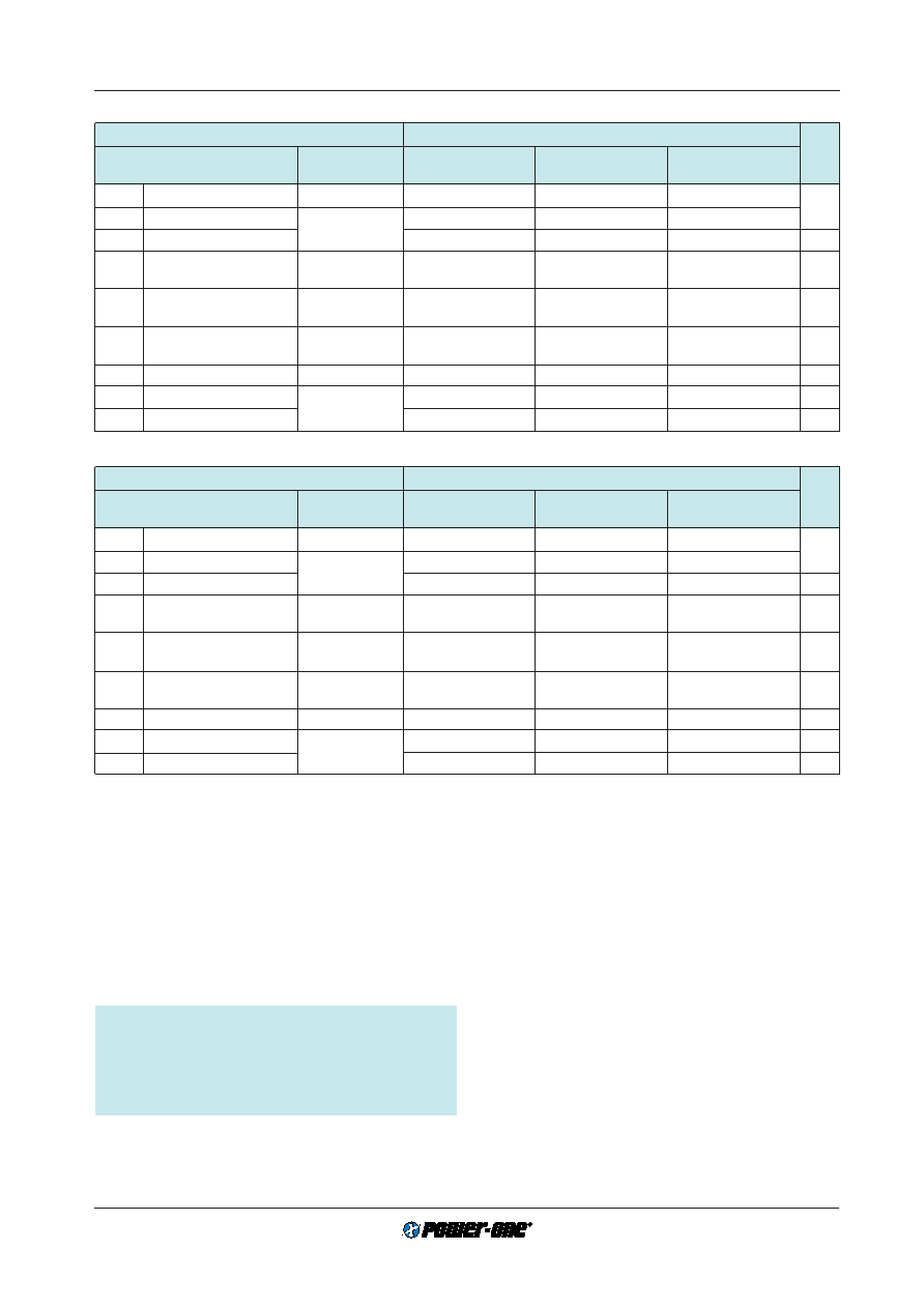
Table 3d: Output data for triple output units
Output
.. IMR 25-051212
Output 1
Output 2
Output 3
Characteristics
Conditions
min
typ
max
min
typ
max
min
typ
max
Unit
Uo
Output voltage
Ui nom, Io nom
4.9
5
5.1
11.76
12
12.24
–11.76 –12 –12.24
V
Uo max
Maximum output voltage
Ui min...Ui max
5.1
15
–15
Io
Output current
800
4000
60
300
500 1
60
300
500 1
mA
uo
Output voltage noise
Ui nom
50
100
150
240
150
240
mVpp
(BW = 20 MHz)
Io nom
DUo U
Static line regulation
Ui min...Ui max
±1
±1%
Io nom
DUo I
Static load regulation
Ui nom
4.9
5
5.1
11.4
12
12.6
–11.4
–12
–12.6
V
(0.2...1)
Io nom
tr
Transient recovery time
Io nom 1/2
500
s
aUo
Temperature coefficient
Ui nom, Io nom
±0.02
%/K
fs
Switching frequency
80
kHz
Table 3e: Output data for triple output units
Output
.. IMR 25-051515-2
Output 1
Output 2
Output 3
Characteristics
Conditions
min
typ
max
min
typ
max
min
typ
max
Unit
Uo
Output voltage
Ui nom, Io nom
4.9
5
5.1
14.7
15
15.3
–14.7
–15
–15.3
V
Uo max
Maximum output voltage
Ui min...Ui max
5.1
18
–18
Io
Output current
700
3500
60
300
500 1
60
300
500 1
mA
uo
Output voltage noise
Ui nom
50
100
200
300
200
300
mVpp
(BW = 20 MHz)
Io nom
DUo U
Static line regulation
Ui min...Ui max
±1
±1%
Io nom
DUo I
Static load regulation
Ui nom
4.9
5
5.1
14.25
15
15.75
–14.25 –15 –15.75
V
(0.2...1)
Io nom
tr
Transient recovery time
Io nom 1/2
500
s
auo
Temperature coefficient
Ui nom, Io nom
±0.02
%/K
fs
Switching frequency
80
kHz
1 Total power may not exceed maximum power as stated in table Type Survey and Key Data.
Thermal Considerations
If a converter is operated, the relationship between the am-
bient temperature
TA and the case temperature TC depends
heavily on the conditions of operation and integration into a
system. The thermal conditions are influenced by input volt-
age, output current, airflow, temperature of surrounding
components and surfaces and the properties of the printed
circuit board. The specified maximum ambient temperature
TA max is therefore only an indicative value and under practi-
cal operating conditions, the ambient temperature
TA may
be higher or lower than this value.
Caution: The case temperature
TC measured at the
Measuring point of case temperature TC (see: Mechani-
cal Data) may under no circumstances exceed the speci-
fied maximum value. The installer must ensure that un-
der all operating conditions
TC remains within the limits
stated in the table:
Temperature specifications.
Connection in Parallel
The current limitation characteristics is fold-back. There-
fore, parallel connection is not possible.
相關(guān)PDF資料 |
PDF描述 |
|---|---|
| 12IMR25-03-2 | Coaxial Cable; Coaxial RG/U Type:6; Impedance:75ohm; Conductor Size AWG:18; No. Strands x Strand Size:Solid; Jacket Material:Polyvinylchloride (PVC); Conductor Material:Steel; Leaded Process Compatible:Yes RoHS Compliant: Yes |
| 12IMR25-05-2 | 1-OUTPUT 25 W DC-DC REG PWR SUPPLY MODULE |
| 12IMR25-051515-2 | 3-OUTPUT 26.5 W DC-DC REG PWR SUPPLY MODULE |
| 12IMR25-051212-2 | 3-OUTPUT 27.2 W DC-DC REG PWR SUPPLY MODULE |
| 12IMR3-03-2 | 1-OUTPUT 2.3 W DC-DC REG PWR SUPPLY MODULE |
相關(guān)代理商/技術(shù)參數(shù) |
參數(shù)描述 |
|---|---|
| 12IMR25-05-2 | 制造商:POWER-ONE 制造商全稱:Power-One 功能描述:25...40 Watt DC-DC Converters |
| 12IMR25-1212-2 | 制造商:POWER-ONE 制造商全稱:Power-One 功能描述:25...40 Watt DC-DC Converters |
| 12IMR25-12-2 | 制造商:POWER-ONE 制造商全稱:Power-One 功能描述:25...40 Watt DC-DC Converters |
| 12IMR25-1515-2 | 制造商:POWER-ONE 制造商全稱:Power-One 功能描述:25...40 Watt DC-DC Converters |
| 12IMR25-15-2 | 制造商:POWER-ONE 制造商全稱:Power-One 功能描述:25...40 Watt DC-DC Converters |
發(fā)布緊急采購,3分鐘左右您將得到回復(fù)。