- 您現(xiàn)在的位置:買賣IC網(wǎng) > PDF目錄62977 > 12IMR6-05-7 1-OUTPUT 5 W DC-DC REG PWR SUPPLY MODULE PDF資料下載
參數(shù)資料
| 型號: | 12IMR6-05-7 |
| 元件分類: | 電源模塊 |
| 英文描述: | 1-OUTPUT 5 W DC-DC REG PWR SUPPLY MODULE |
| 文件頁數(shù): | 2/6頁 |
| 文件大小: | 171K |
| 代理商: | 12IMR6-05-7 |

Board Mountable
DC-DC Converters
IMR 6 Series
Edition 5/5.2000
2/6
Table 2b: Input data
Input
40 IMR 6
48 IMR 6
Characteristics
Conditions
min
typ
max
min
typ
max
Unit
Ui
Input voltage range
TA min...TA max
20
60
36
72
V DC
Ui nom
Nominal input voltage
Io = 0...Io nom
36
48
Ui
Input voltage without
0
75
0
75
damage
Ii 0
No load input current
Ui nom, Io = 0
26
mA
Ii L
Input current limitation
Ui nom, full load
1.25
P i nom
1.25
P i nom
W
response
Ui rev
Reverse input voltage
Ui = negative or
shunt diode
protection
reverse polarity
use external fuse
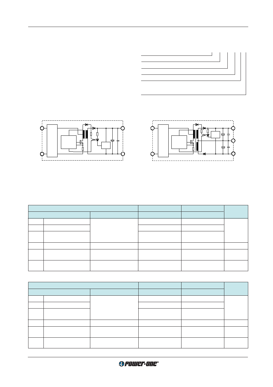
Type Key
24 IMR 6 - 12 12 -2
Nominal input voltage in volt ................................... 12...48
Series .......................................................................... IMR
Nominal output power in watt ........................................... 6
Nominal output voltage for output 1 in volt .............. 05...15
Nominal output voltage for output 2 in volt .............. 05...15
Operational ambient temperature range
TA
–10...50
°C .................................................. -2
–25...71
°C .................................................. -7
Vi+
Vo–
Vi–
Vo+
Control
Shunt
diode,
Filter
COM
03035
Ref.
Vi+
Vo–
Vi–
Vo+
Ref.
Control
Shunt
diode,
Filter
03034
Fig. 2:
Dual output converter block diagram
Fig. 1:
Single output converter block diagram
Functional Description
Electrical Input Data
General condition:
TA = 25
°C unless otherwise specified
Table 2a: Input data
Input
12 IMR 6
24 IMR 6
Characteristics
Conditions
min
typ
max
min
typ
max
Unit
Ui
Input voltage range
TA min...TA max
918
18
36
V DC
Ui nom
Nominal input voltage
Io = 0...Io nom
12
24
Ui
Input voltage without
0
22
0
40
damage
Ii 0
No load input current
Ui nom, Io = 0
22
26
mA
Ii L
Input current limitation
Ui nom, full load
1.25
P i nom
1.25
P i nom
W
response
Ui rev
Reverse input voltage
Ui = negative or
shunt diode
protection
reverse polarity
use external fuse
相關(guān)PDF資料 |
PDF描述 |
|---|---|
| 12IMR6-15-2 | 1-OUTPUT 6 W DC-DC REG PWR SUPPLY MODULE |
| 12IMR6-0505-2 | 2-OUTPUT 5 W DC-DC REG PWR SUPPLY MODULE |
| 12IMR6-03-7 | 1-OUTPUT 5 W DC-DC REG PWR SUPPLY MODULE |
| 12IMR6-05-2 | 1-OUTPUT 5 W DC-DC REG PWR SUPPLY MODULE |
| 12IMR6-15-2 | 1-OUTPUT 6 W DC-DC REG PWR SUPPLY MODULE |
相關(guān)代理商/技術(shù)參數(shù) |
參數(shù)描述 |
|---|---|
| 12IMR6-1212-2 | 制造商:POWER-ONE 制造商全稱:Power-One 功能描述:3...15 Watt DC-DC Converter |
| 12IMR6-12-2 | 制造商:POWER-ONE 制造商全稱:Power-One 功能描述:3...15 Watt DC-DC Converter |
| 12IMR6-1515-2 | 制造商:POWER-ONE 制造商全稱:Power-One 功能描述:3...15 Watt DC-DC Converter |
| 12IMR6-15-2 | 制造商:POWER-ONE 制造商全稱:Power-One 功能描述:3...15 Watt DC-DC Converter |
| 12INBLACK | 制造商: 功能描述: 制造商:undefined 功能描述: |
發(fā)布緊急采購,3分鐘左右您將得到回復(fù)。