- 您現(xiàn)在的位置:買賣IC網(wǎng) > PDF目錄293740 > 1340CNPC (TRIQUINT SEMICONDUCTOR INC) RECEIVER PDF資料下載
參數(shù)資料
| 型號: | 1340CNPC |
| 廠商: | TRIQUINT SEMICONDUCTOR INC |
| 元件分類: | 數(shù)字傳輸電路 |
| 英文描述: | RECEIVER |
| 封裝: | PLASTIC, DIP-20 |
| 文件頁數(shù): | 7/12頁 |
| 文件大小: | 221K |
| 代理商: | 1340CNPC |

Data Sheet
1340-Type Lightwave Receiver
January 2000
4
Lucent Technologies Inc.
Data and Flag Outputs (continued)
The FLAG and FLAG outputs of the OC-3/STM-1
155 Mbits/s version of the 1340 receiver are PECL
logic levels driven by open emitter transistors with the
same characteristics as the data outputs. These out-
puts must be properly terminated in order to obtain the
correct logic levels. Since the FLAG function is basi-
cally a dc switch that indicates the loss of optical input
signal, it can be interfaced to much slower TTL or
CMOS logic circuits.
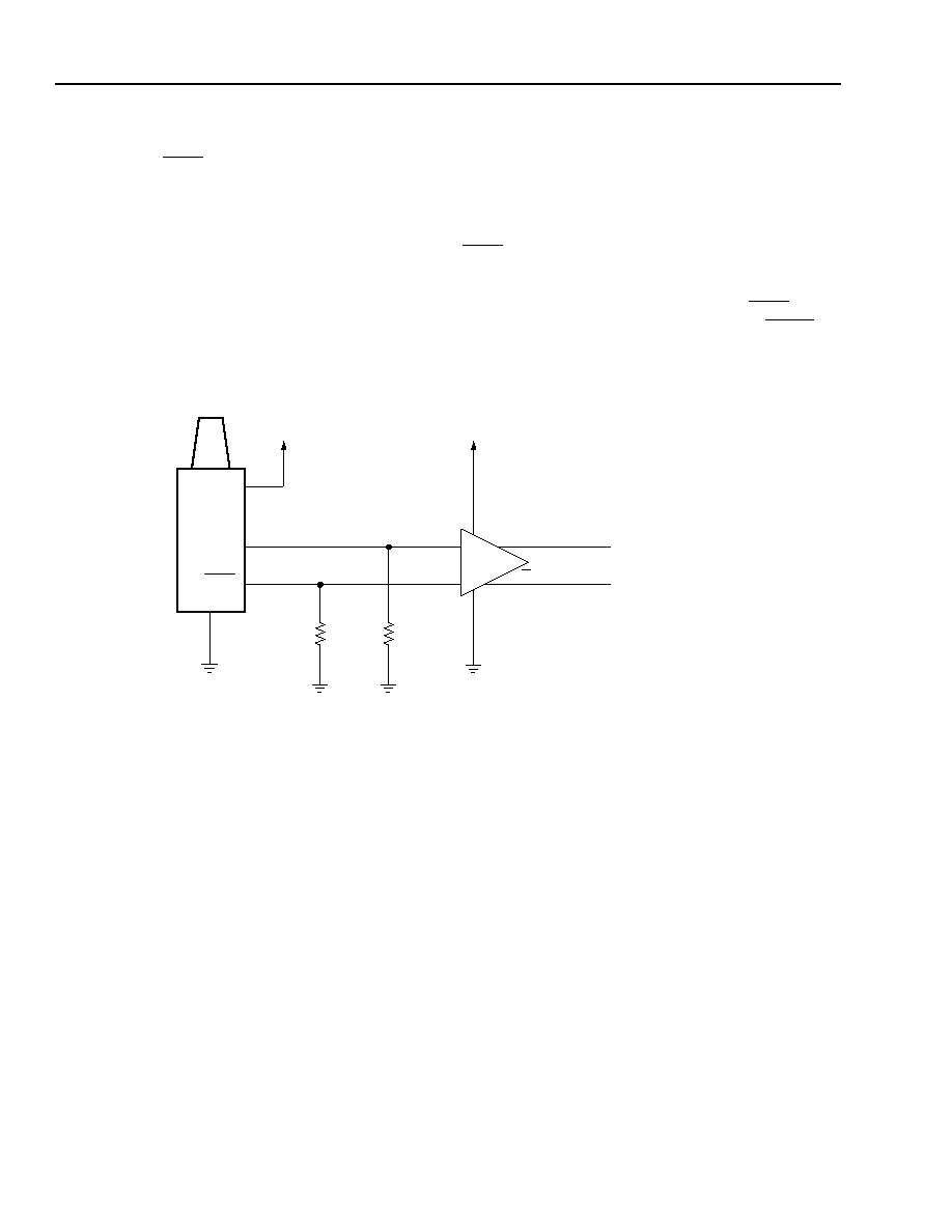
The circuit shown in Figure 2 provides one example of
how to create a TTL logic output from the PECL FLAG
output signal. The outputs of the LT1016 are TTL-com-
patible and provide both true and inverted logic levels.
The Q output of this circuit will be a TTL high (>2.5 V)
when the 1340 is receiving an optical signal greater
than the FLAG switching threshold and will be a TTL
low (<0.4 V) whenever the optical signal is absent or is
below the FLAG switching threshold. The FLAG and
FLAG outputs of the OC-12/STM-4 and 1.25 Gbits/s
receivers are 5 V TTL logic level compatible. The FLAG
output is provided directly by the comparator IC. How-
ever, the FLAG output is derived from the FLAG output
through an inverter. Excessive loading of the FLAG out-
put can cause the FLAG output to malfunction.
1-800(C).a
* Part available from Linear Technology Corporation of Milpitas, CA 95035.
Figure 2. Converting PECL FLAG Outputs to TTL
11
12
14
10 k
TTL (TRUE)
TTL (INVERTED)
LT1016*
1340
RX
FLAG
+5 V
10 k
+
–
Q
相關(guān)PDF資料 |
PDF描述 |
|---|---|
| 1340CMPC | RECEIVER |
| 1340CCPC | RECEIVER |
| 1340CBPC | RECEIVER |
| 1340CAPC | RECEIVER |
| 1345CNPC | RECEIVER, PDFO |
相關(guān)代理商/技術(shù)參數(shù) |
參數(shù)描述 |
|---|---|
| 1340FAPC | 制造商:AGERE 制造商全稱:AGERE 功能描述:1340-Type Lightwave Receiver |
| 1340FBPC | 制造商:AGERE 制造商全稱:AGERE 功能描述:1340-Type Lightwave Receiver |
| 1340FCPC | 制造商:AGERE 制造商全稱:AGERE 功能描述:1340-Type Lightwave Receiver |
| 1340FMPC | 制造商:AGERE 制造商全稱:AGERE 功能描述:1340-Type Lightwave Receiver |
| 1340FNPC | 制造商:AGERE 制造商全稱:AGERE 功能描述:1340-Type Lightwave Receiver |
發(fā)布緊急采購,3分鐘左右您將得到回復(fù)。