- 您現(xiàn)在的位置:買賣IC網(wǎng) > PDF目錄351626 > 1392019-1 (Tyco Electronics) Special Coaxial Contacts PDF資料下載
參數(shù)資料
| 型號(hào): | 1392019-1 |
| 廠商: | Tyco Electronics |
| 元件分類: | RF連接器 |
| 英文描述: | Special Coaxial Contacts |
| 中文描述: | Special Coaxial Contacts |
| 文件頁(yè)數(shù): | 1/4頁(yè) |
| 文件大小: | 289K |
| 代理商: | 1392019-1 |
238
Catalog 1307191
Dimensions are in millimeters
Dimensions are shown for
USA: 1-800-522-6752
South America: 55-11-2103-6000
Revised 3-07
and inches unless otherwise
reference purposes only.
Canada: 1-905-470-4425
Hong Kong: 852-2735-1628
specified. Values in brackets
Specifications subject
Mexico: 01-800-733-8926
Japan: 81-44-844-8013
www.tycoelectronics.com
are standard equivalents.
to change.
C. America: 52-55-1106-0803
UK: 44-8706-080-208
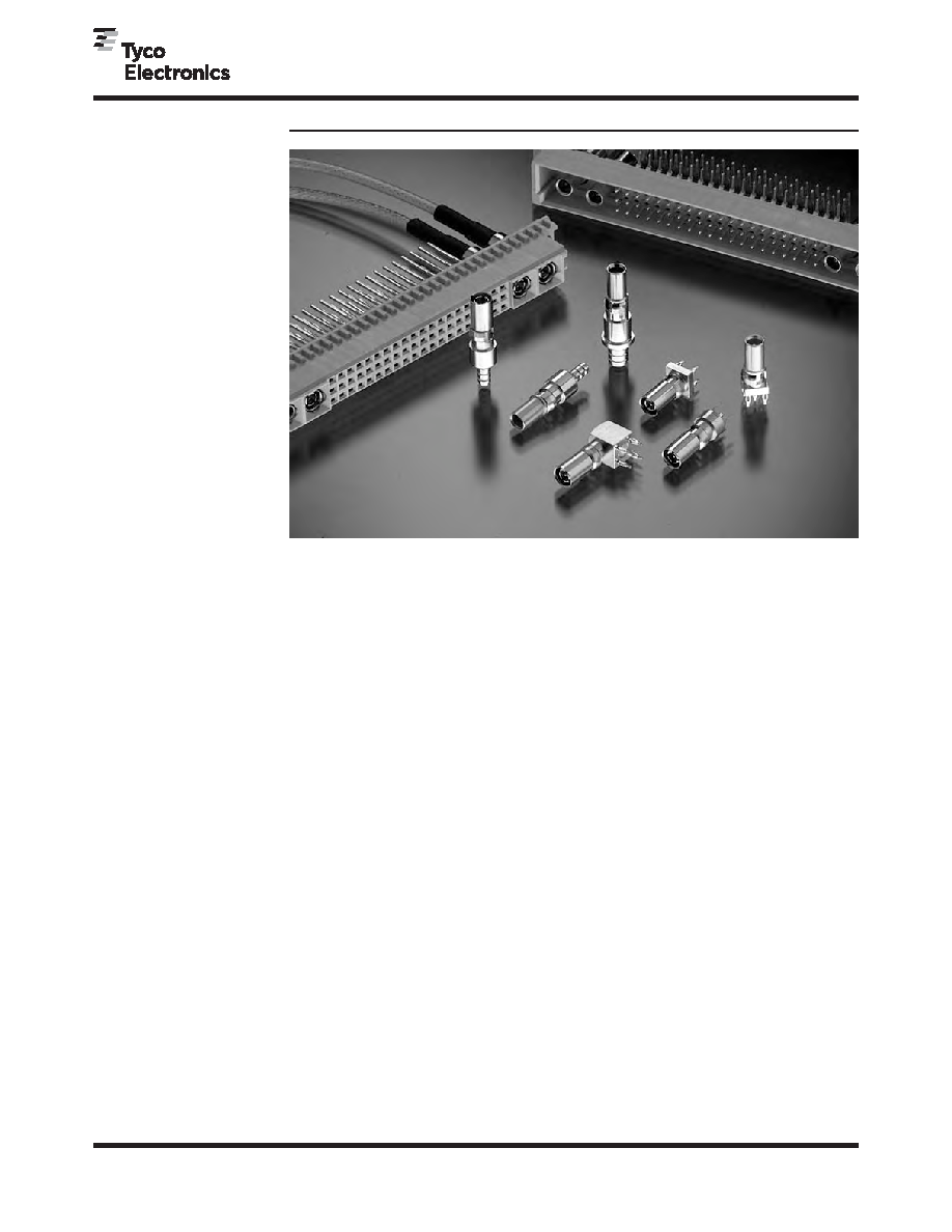
RF Coax Connectors
DIN Inserts
Coaxial inserts according
to CECC 22 330 and high-
current inserts (CECC spec-
ification under preparation)
can be used in conjunction
with a DIN 41612 style M
contact base (CECC 75
101-801), SIEDECON,
and Z-PACK 2mm HM
connectors.
Coaxial inserts have a con-
tact system based on the
pin-socket principle with the
same dimensions as the
Series 1.0/2.3 coaxial con-
nectors and are plug-com-
patible. The product family
is represented by various
50
and 75 styles that can
be used far into the GHz
range. The high mounting
density (pitch between adja-
cent contacts starting at 7.5
mm) and installation into the
contact base, by means of
a “snap-in” lock, make the
inserts particularly well
suited for applications.
Due to the centering,
– coaxial plugs are
installed in contact bases
with audio-frequency
(AF) female contacts
– coaxial jacks are
installed in contact bases
with AF male contacts.
The high-quality materials
used with coaxial inserts
ensure a high grade of
service even in an industrial
atmosphere.
Technical Data
Electrical and mechanical
characteristics of coaxial
inserts in accordance with DIN
41626 Part 2 and CECC 22 330
Characteristic Impedance —
50/75
Frequency Range — up to 2 GHz
Reflection Factor Up To 2 GHz 1 —
≤ 0.10
Insulation Resistance —
Initial value —
≥ 1 G
After stressing —
≥ 200 M
Screening Effectiveness —
≥ 70 dB
Inner Conductor Contact Resistance
After Stressing —
≤ 10 m
Outer Conductor Continuity After
Stressing —
≤ 7.5 m
Voltage Proof 2 —
Flexible Cables (RG 316)
At sea level — 750 V, 50 Hz
At 20 km altitude — 150 V, 50 Hz
Working Voltage 2 —
Flexible Cables (RG 316)
At sea level — 350 V, 50 Hz
At 20 km altitude — 65 V, 50 Hz
Service Life — 500 cycles
Climatic Category — 55/125/56
Notes
1 Guideline dimensions, depending
on cable type and connector style.
2 Some cable types suitable for use
with these connectors have lower
characteristic values than speci-
fied here.
Product Facts
■
Meets requirements of DIN
41626 and CECC 22330
■
Suitable for DIN 41612 Type
M Connectors (Eurocard),
Siedecon, and Z-PACK 2mm
HM Connectors
■
Meets DIN Performance
Level II
■
Crimp termination for inner
and outer conductors (cable
mount only) eliminates the
need for solder
■
Right-angle and vertical
style board mount pin and
socket contacts
■
Board mount product avail-
able with both solder and
compliant tails
■
Straight cable mount pin
and socket contacts for
RG 316, and RG 179 cable
■
Contact impedance of 50
and 75 ohms for cable
mount and 50 ohms for
board mount
相關(guān)PDF資料 |
PDF描述 |
|---|---|
| 1392020-1 | Type C Coax, Standard DIN Contacts |
| 1393668-4 | Special Coaxial Contacts |
| 1393668-7 | Special Coaxial Contacts |
| 1393668-8 | Special Coaxial Contacts |
| 1393672-3 | Series 1.6/5.6 mS |
相關(guān)代理商/技術(shù)參數(shù) |
參數(shù)描述 |
|---|---|
| 1392020-1 | 制造商:TE Connectivity 功能描述:GEHAUSEKUPPLER - Bulk |
| 139-203 | 制造商:Mitutoyo Corporation 功能描述:MIC, TUB INSIDE |
| 1392036-1 | 制造商:TE Connectivity 功能描述:Z-PACK/A M-HDR 154 POS - Bulk |
| 1392037-1 | 制造商:TE Connectivity 功能描述:Z-PACK/B M-HDR 154 POS - Bulk |
| 1392039-1 | 制造商:TE Connectivity 功能描述:Z-PACK/A M-HDR 154 POS - Bulk |
發(fā)布緊急采購(gòu),3分鐘左右您將得到回復(fù)。