- 您現(xiàn)在的位置:買賣IC網(wǎng) > PDF目錄2021 > 19245 (Desco)TESTER LOW RESISTANCE PDF資料下載
參數(shù)資料
| 型號: | 19245 |
| 廠商: | Desco |
| 文件頁數(shù): | 2/4頁 |
| 文件大小: | 0K |
| 描述: | TESTER LOW RESISTANCE |
| 標(biāo)準(zhǔn)包裝: | 1 |
| 類型: | 測試器 |
| 使用: | 靜電控制設(shè)備測試 |
| 特點: | NIST 溯源 |
| 電源類型: | 電池 |
| 包括: | 電池,證書,電線 |
| 其它名稱: | 16-1164 |

DESCO WEST
- 3651 Walnut Avenue, Chino, CA 91710 (909) 627-8178 Fax (909) 627-7449
DESCO EAST
- One Colgate Way, Canton, MA 02021-1407 (781) 821-8370 Fax (781) 575-0172 Website: Desco.com
TB-3055
Page 2 of 4
2012 DESCO INDUSTRIES, INC.
Employee Owned
E. Low Battery LED:
LED illuminates when the battery
needs to be replaced.
F. 6 Foot Coiled Cord:
Insulation black color PVC
G. Banana Plug:
Industrial Standard .175" (4.4 mm) Banana
Plug, fits banana jack ≥ .157".
Operation
USING THE TESTER
1. Use the slide switch to select a test range.
2. Connect the coil cord banana plug end to known ground.
Use adapters where needed. NOTE: The Desco Low
Resistance Tester may be used with an outlet polarity
checker such as the Desco 19219 to determine a known
ground.
3. Connect or touch the tester end to a banana jack or
other equipment that is being tested for resistance to
ground.
4. Press and hold the test button.
5. An audio and visual indication will activate for a PASS
condition.
6. A FAIL condition is indicated when the buzzer does not
sound and the PASS does not illuminate.
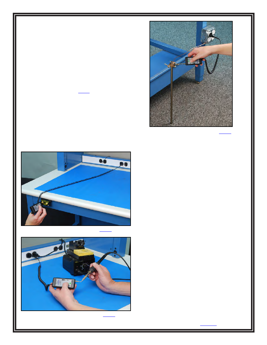
Figure 3. Testing ground points with the 19245 tester
Example of Test Range Uses
<1 OHM Range
- ESD Technical element Grounding Conductors:
Banana Jacks, Grounding Blocks, Mat Ground Cords
ANSI/ESD S6.1 Grounding, sections 6.4 Technical
Elements,
6.4.1, 6.4.2 and 6.4.3
- New AC Powered Hand Tools
ESD Handbook ESD TR20.20 section 5.5.2.2 Electrical
Hand Tools
<2 OHM
- Soldering Irons
ESD Handbook ESD TR20.20 section 5.5.2.2 Electrical
Hand Tools
- Other AC Powered Hand Tools
ESD Handbook ESD TR20.20 section 5.5.2.2 Electrical
Hand Tools
<20 OHM
- Soldering iron verification
ESD Handbook ESD TR20.20 section 5.5.2.2 Electrical
Hand Tools
- Auxiliary grounds (ground rods)
ANSI/ESD S20.20*
* ANSI/ESD S20.20 requires <25 ohms from the Auxiliary
Ground to the Equipment Grounding Conductor. Desco’s
Low Resistance Tester only tests to <20 ohms. In cases
of a no pass result with the Low Resistance Tester when
testing an Auxiliary Ground, an Ohm meter should used to
determine the actual resistance from the Auxiliary Ground to
the Equipment Grounding Conductor
Figure 4. Testing a soldering iron with the 19245 tester
Figure 5. Testing auxiliary ground with the 19245 tester
相關(guān)PDF資料 |
PDF描述 |
|---|---|
| 19253 | TESTER COMBO WS&FS W/ PLATE |
| 19276 | TESTER X3 COMBO PROG W/DL PLATE |
| 19350 | TESTER W/S 2 STATE TOUCH NIST |
| 19430 | STATIC LOCATOR DIGITAL |
| 19447 | KIT COMPLETE FLD MTR/ION TEST |
相關(guān)代理商/技術(shù)參數(shù) |
參數(shù)描述 |
|---|---|
| 1924500000 | 制造商:Weidmuller 功能描述:CONN DIODE TERM BLOCKS 6 POS ST 20A - Bulk 制造商:Weidmuller 功能描述:TERMINAL ZDK 2.5/3AN BL |
| 19245-0002 | 制造商:MOLEX 功能描述: |
| 19245-0003 | 制造商:MOLEX 功能描述: |
| 19245-0038 | 制造商:MOLEX 功能描述: |
| 19245-0039 | 制造商:MOLEX 功能描述: |
發(fā)布緊急采購,3分鐘左右您將得到回復(fù)。