- 您現在的位置:買賣IC網 > PDF目錄371381 > 23L8100-15 (Macronix International Co., Ltd.) 8M-BIT MASK ROM(8/16 BIT OUTPUT) PDF資料下載
參數資料
| 型號: | 23L8100-15 |
| 廠商: | Macronix International Co., Ltd. |
| 英文描述: | 8M-BIT MASK ROM(8/16 BIT OUTPUT) |
| 中文描述: | 800萬位掩碼光盤(8 / 16位輸出) |
| 文件頁數: | 3/9頁 |
| 文件大小: | 747K |
| 代理商: | 23L8100-15 |

3
P/N:PM0464
REV. 1.7, AUG. 20, 2001
MX23L8100
DC CHARACTERISTICS
(Ta = 0
°
C ~ 70
°
C, VCC = 3.3V
±
10%)
Item
Output High Voltage
Output Low Voltage
Input High Voltage
Input Low Voltage
Input Leakage Current
Output Leakage Current
Operating Current
Standby Current (TTL)
Standby Current (CMOS)
Input Capacitance
Output Capacitance
Symbol
VOH
VOL
VIH
VIL
ILI
ILO
ICC1
ISTB1
ISTB2
CIN
COUT
MIN.
24V
-
2.2V
-0.3V
-
-
-
-
-
-
-
MAX.
-
0.4V
VCC+0.3V
0.8V
5uA
5uA
20mA
1mA
5uA
10pF
10pF
Conditions
IOH = -0.4mA
IOL = 1.6mA
0V, VCC
0V, VCC
f=10MHz, all output open
CE=VIH
CE> VCC - 0.2V
Ta = 25
°
C, f = 1MHZ
Ta = 25
°
C, f = 1MHZ
AC CHARACTERISTICS
(Ta = 0
°
C ~ 70
°
C, VCC = 3.3V
±
10%)
Item
Symbol
23L8100-10
MIN.
100ns
-
-
-
0ns
-
23L8100-12
MIN.
120ns
-
-
-
0ns
-
23L8100-15
MIN.
150ns
-
-
-
0ns
-
MAX.
-
100ns
100ns
50ns
-
20ns
MAX.
-
120ns
120ns
60ns
-
20ns
MAX.
-
150ns
150ns
70ns
-
20ns
Read Cycle Time
Address Access Time
Chip Enable Access Time
Output Enable Time
Output Hold After Address
Output High Z Delay
tRC
tAA
tACE
tOE
tOH
tHZ
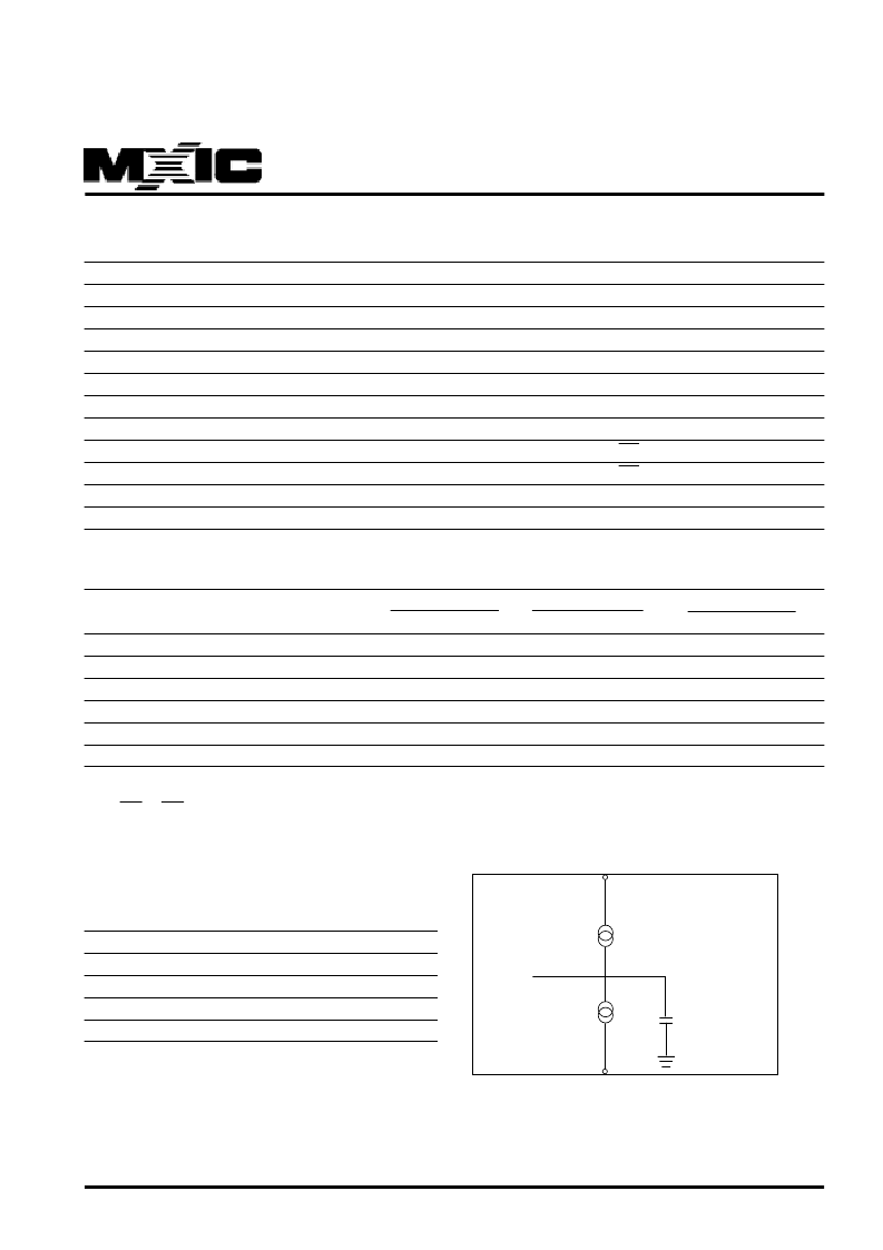
AC Test Conditions
Input Pulse Levels
Input Rise and Fall Times
Input Timing Level
Output Timing Level
Output Load
0.4V~2.4V
10ns
1.4V
1.4V
See Figure
Note:Output high-impedance delay (tHZ) is measured
from OE or CE going high, and this parameter guaran-
teed by design over the full voltage and temperature op-
erating range - not tested.
Note:No output loading is present in tester load board.
Active loading is used and under software programming control.
Output loading capacitance includes load board's and all stray capacitance.
DOUT
C<100pF
IOL (load)=1.6mA
IOH (load)=-0.4mA
相關PDF資料 |
PDF描述 |
|---|---|
| 23L8102-12 | 8M-BIT MASK ROM |
| 23L8102-70 | 8M-BIT MASK ROM |
| 23L8102-90 | 8M-BIT MASK ROM |
| 23L8103-12 | 8M-BIT MASK ROM |
| 23L8103-70 | 8M-BIT MASK ROM |
相關代理商/技術參數 |
參數描述 |
|---|---|
| 23L8102-12 | 制造商:MCNIX 制造商全稱:Macronix International 功能描述:8M-BIT MASK ROM |
| 23L8102-70 | 制造商:MCNIX 制造商全稱:Macronix International 功能描述:8M-BIT MASK ROM |
| 23L8102-90 | 制造商:MCNIX 制造商全稱:Macronix International 功能描述:8M-BIT MASK ROM |
| 23L8103-12 | 制造商:MCNIX 制造商全稱:Macronix International 功能描述:8M-BIT MASK ROM |
| 23L8103-70 | 制造商:MCNIX 制造商全稱:Macronix International 功能描述:8M-BIT MASK ROM |
發(fā)布緊急采購,3分鐘左右您將得到回復。