- 您現(xiàn)在的位置:買賣IC網(wǎng) > PDF目錄222231 > 24Z4665E TELECOM TRANSFORMER PDF資料下載
參數(shù)資料
| 型號: | 24Z4665E |
| 元件分類: | 電信用變壓器 |
| 英文描述: | TELECOM TRANSFORMER |
| 文件頁數(shù): | 1/1頁 |
| 文件大?。?/td> | 18K |
| 代理商: | 24Z4665E |

Vitec Electronics Corporation
Communications Products
04/96
24Z4651
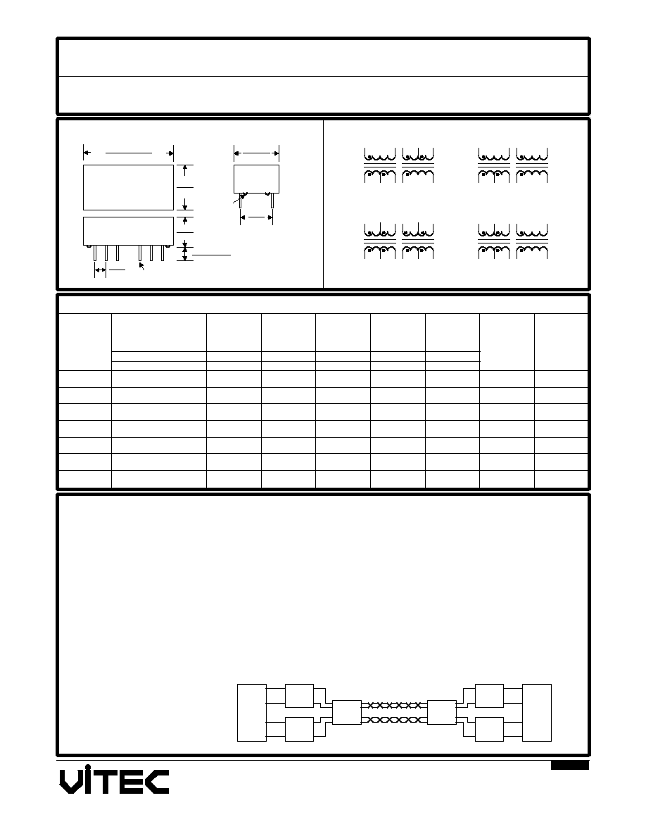
Vitec's T1/E1 Carrier Transformers are specifically designed for use in 1.544 MHz (T1) and 2.048 MHz (E1) interface
applications. The products are offered in single or dual packages that are printed-circuit board mountable. The
transformers have been designed to comply with CCITT G.703 and other international safety standards.
Some transformer models can be used for T1 (100 Ohms) and E1 (75 and 120 Ohms). Models 16Z5953 and 24Z4666
provide two ratios (for Transmit) that makes them suitable for use in either 75 Ohms (1:1) or 120 Ohms (1:1.266)
applications. For extended temperature (-40oC to +85oC) models add an "E" suffix to part number.
Common Mode Chokes for T1/E1 and ISDN applications:
Vitec's common mode chokes are designed to reduce common mode noise in digital telecommunications lines. These
chokes can be used with Vitec's T1/E1 and ISDN transformers, and provide an effective means to comply with
national and international regulations on EMI. Request Vitec catalog information on series 24Z4681 and 24Z4688.
IC
XMIT
RCV
XFMR
Choke
XFMR
IC
RCV
XMIT
24Z4652
24Z4654
24Z4663
24Z4664
24Z4665
24Z4666
VITEC
24Z46XX
xxxxx
1
7
0.800 MAX
20.30 MAX
0.390 MAX
9.90 MAX
Dimensions
Inches/mm
+/- 0.01"
Unless noted
14
8
0.015
Standoffs
0.300
7.60
0.390 MAX
9.90
0.250 MAX
6.40
0.120 - 0.140
3.00 - 3.60
0.100
2.54
#24 Leads
C
A
B
D
10
9
8
14
12
5
7
1
2
3
10
8
14
12
5
7
1
2
3
10
8
14
13
12
5
7
1
2
3
10
8
14
12
5
6
7
1
2
3
9
13
14-12, 5-7
1-3, 10-8
1-3, 5-7
14-12, 5-7
1-3, 5-7
2A
2B
2D
2C
2A
2C
1.00
1.80
1.10 & 0.70
1.00 & 1.10
0.70 & 1.10
1.10
1.00 & 0.90
0.70
0.80
0.70
0.50
0.70
30
35
30
35 & 30
35 & 40
35 & 30
0.50
0.50 & 0.80
0.55 & 0.50
0.80
0.50 & 0.40
0.60 & 0.50
0.80
1.20
1.50 & 1.20
1.20
1:2CT&1:2CT
1:2CT&1:1.36
1CT:2CT&1:1
1CT:2.3CT&1CT:2CT
1:1:1.266&1:2CT
1:1.15CT&1:2CT
1CT:1.53CT&1CT:2CT
SCHEMATICS
DRAWING
T1/E1 INTERFACE TRANSFORMERS
1500 VRMS, DUAL PACKAGES
ELECTRICAL CHARACTERISTICS @ 25oC
Part
Number
Turns
Ratio
OCL
Primary
DCR
Primary
Pins
Secondary
DCR
GENERAL INFORMATION
Typical Application
Case &
Schematic
Pri/Sec
CC
Pri/Sec
LL
Ohms
MAX
Ohms
pF
uH
mH
Ratio
+/- 5%
相關(guān)PDF資料 |
PDF描述 |
|---|---|
| 24Z4666E | TELECOM TRANSFORMER |
| 251-5949-02-0602 | ZIP51, IC SOCKET |
| 25139NLDH6X693 | SLIDE SWITCH, SPDT, LATCHED, 0.1A, 30VDC, THROUGH HOLE-STRAIGHT |
| 25349NLDX601 | SLIDE SWITCH, DPDT, LATCHED, 0.1A, 30VDC, THROUGH HOLE-RIGHT ANGLE |
| 25436NAH6X601 | SLIDE SWITCH, SPDT, LATCHED, 1A, 30VDC, THROUGH HOLE-STRAIGHT |
相關(guān)代理商/技術(shù)參數(shù) |
參數(shù)描述 |
|---|---|
| 24Z504AR | 制造商:Cornell Dubilier Electronics 功能描述: 制造商:Mallory Sonalert Products Inc 功能描述: |
| 24ZDSLF007 | 制造商:Madison Cable / TE 功能描述: |
| 25 | 功能描述:電纜組件 S. F. JAX RoHS:否 制造商:Molex 產(chǎn)品:Power Assemblies 類型:Cable Assembly 連接器端口 A:No Connector 連接器端口 A 管腳計數(shù):4 連接器端口 B:No Connector 連接器端口 B 管腳計數(shù): 型式:Male 線規(guī) - 美國線規(guī)(AWG):20, 28 長度:0.305 m 顏色:Black, Red |
| 25 0.75"X650" | 功能描述:SCOTCH MULTITASK TAPE 25 3/4" 制造商:3m 系列:* 零件狀態(tài):在售 標(biāo)準(zhǔn)包裝:12 |
| 25 01 160 | 制造商:Knipex 功能描述:Bulk |
發(fā)布緊急采購,3分鐘左右您將得到回復(fù)。