- 您現(xiàn)在的位置:買賣IC網(wǎng) > PDF目錄371431 > 2842B (Texas Instruments, Inc.) HIGH-PERFORMANCE CURRENT-MODE PWM CONTROLLERS PDF資料下載
參數(shù)資料
| 型號(hào): | 2842B |
| 廠商: | Texas Instruments, Inc. |
| 英文描述: | HIGH-PERFORMANCE CURRENT-MODE PWM CONTROLLERS |
| 中文描述: | 高性能的電流模式PWM控制器 |
| 文件頁(yè)數(shù): | 5/21頁(yè) |
| 文件大小: | 336K |
| 代理商: | 2842B |
第1頁(yè)第2頁(yè)第3頁(yè)第4頁(yè)當(dāng)前第5頁(yè)第6頁(yè)第7頁(yè)第8頁(yè)第9頁(yè)第10頁(yè)第11頁(yè)第12頁(yè)第13頁(yè)第14頁(yè)第15頁(yè)第16頁(yè)第17頁(yè)第18頁(yè)第19頁(yè)第20頁(yè)第21頁(yè)

www.ti.com
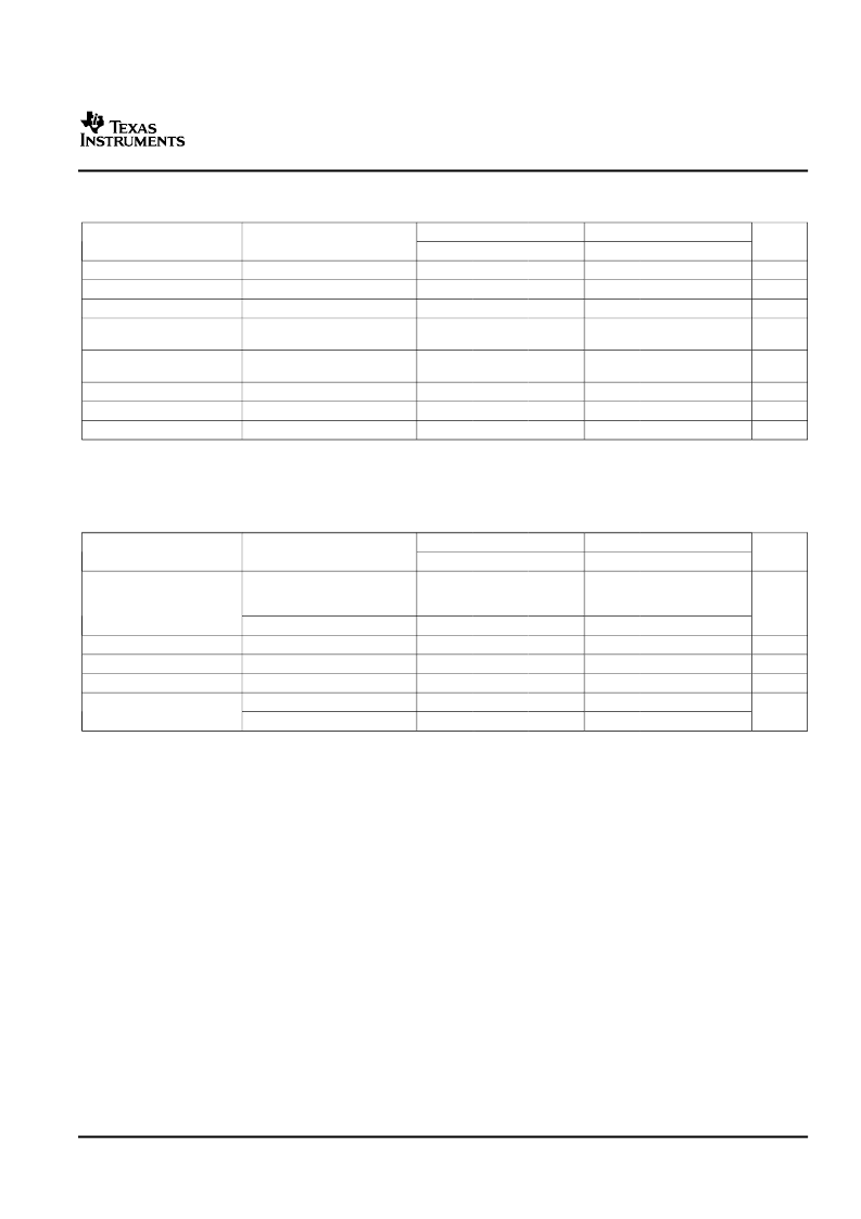
Reference Section Electrical Characteristics
V
CC
= 15 V
(1)
, R
T
= 10 k
, C
T
= 3.3 nF, over recommended operating free-air temperature range (unless otherwise specified)
Oscillator Section
(1)
Electrical Characteristics
V
CC
= 15 V
(2)
, R
T
= 10 k
, C
T
= 3.3 nF, over recommended operating free-air temperature range (unless otherwise specified)
TL284xB, TL384xB
HIGH-PERFORMANCE CURRENT-MODE PWM CONTROLLERS
SLVS610A–AUGUST 2006–REVISED SEPTEMBER 2006
TL284xB
TYP
(2)
TL384xB
TYP
(2)
PARAMETER
TEST CONDITIONS
UNIT
MIN
4.95
MAX
5.05
20
25
MIN
4.9
MAX
5.1
20
25
Output voltage
Line regulation
Load regulation
Average temperature
coefficient of output voltage
Output voltage, worst-case
variation
Output noise voltage
Output-voltage long-term drift After 1000 h at T
J
= 25
°
C
Short-circuit output current
I
O
= 1 mA, T
J
= 25
°
C
V
CC
= 12 V to 25 V
I
O
= 1 mA to 20 mA
5
6
6
5
6
6
V
mV
mV
0.2
0.4
0.2
0.4
mV/
°
C
V
CC
= 12 V to 25 V,
I
O
= 1 mA to 20 mA
f = 10 Hz to 10 kHz, T
J
= 25
°
C
4.9
5.1
4.82
5.18
V
50
50
μ
V
mV
mA
5
25
5
25
–30
–100
–180
–30
–100
–180
(1)
(2)
Adjust V
above the start threshold before setting it to 15 V.
All typical values are at T
J
= 25
°
C.
TL284xB
TYP
(3)
TL384xB
TYP
(3)
PARAMETER
TEST CONDITIONS
UNIT
MIN
MAX
MIN
MAX
T
J
= 25
°
C, R
= 62 k
,
C
= 1 nF, Min = 225 kHz,
Max = 275 kHz
T
J
= Full range
V
CC
= 12 V to 25 V
49
52
55
49
52
55
Initial accuracy
kHz
48
56
48
56
Voltage stability
Temperature stability
Amplitude
0.2
1
0.2
1
%
%
V
5
5
Peak to peak
T
J
= 25
°
C, R
T
/C
T
= 2 V
R
T
/C
T
= 2 V
1.7
8.3
1.7
8.3
7.8
7.5
8.8
8.8
7.8
7.6
8.8
8.8
Discharge current
mA
(1)
Output frequency equals oscillator frequency for the TL3842B and TL3843B. Output frequency is one-half the oscillator frequency for the
TL3844B and TL3845B.
Adjust V
above the start threshold before setting it to 15 V.
All typical values are at T
J
= 25
°
C.
(2)
(3)
5
Submit Documentation Feedback
相關(guān)PDF資料 |
PDF描述 |
|---|---|
| 2843B | HIGH-PERFORMANCE CURRENT-MODE PWM CONTROLLERS |
| 2844B | HIGH-PERFORMANCE CURRENT-MODE PWM CONTROLLERS |
| 2845B | HIGH-PERFORMANCE CURRENT-MODE PWM CONTROLLERS |
| 2843 | SICHTSCHEIBE KLASSE 1 METEOR 1900 |
| 2844 | SICHTSCHEIBE KLASSE 2 METEOR 1900 |
相關(guān)代理商/技術(shù)參數(shù) |
參數(shù)描述 |
|---|---|
| 2842F | 制造商:JT&T Products 功能描述: |
| 2842S024C | 制造商:FAULHABER 功能描述: |
| 2842SL | 制造商:FUNG YIP ELECTRICAL 功能描述:MULTI SOCKET 2 GANG |
| 2843 | 制造商:Altech Corporation 功能描述:Ferrules Terminal 16AWG F 18mm 4mm Tin |
| 2843.0 | 制造商:ALTECH CORP 功能描述:Ferrule; 16 AWG; H 1.5/12; 0.47 in.; 0.71 in.; 0.47 in. L x 0.08 in. Dia. |
發(fā)布緊急采購(gòu),3分鐘左右您將得到回復(fù)。