- 您現(xiàn)在的位置:買賣IC網(wǎng) > PDF目錄371438 > 2993 (Allegro MicroSystems, Inc.) DUAL H-BRIDGE MOTOR DRIVERS PDF資料下載
參數(shù)資料
| 型號(hào): | 2993 |
| 廠商: | Allegro MicroSystems, Inc. |
| 元件分類: | 基準(zhǔn)電壓源/電流源 |
| 英文描述: | DUAL H-BRIDGE MOTOR DRIVERS |
| 中文描述: | 雙H橋電機(jī)驅(qū)動(dòng)器 |
| 文件頁數(shù): | 1/8頁 |
| 文件大小: | 116K |
| 代理商: | 2993 |

2993
DUAL H-BRIDGE
MOTOR DRIVERS
DSCONTNUEDPRODUCT
I
TTL/NMOS/CMOS Compatible Inputs
I
Low Input Current
I
Internal Clamp Diodes
I
Automotive Capable
applied without logic supply voltage present.
Always order by complete part number:
—FORREFERENCEONLY
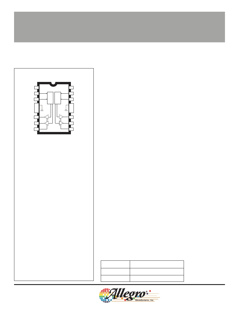
B
1
2
3
4
5
6
7
8
PHASE
GROUND
GROUND
OUT
OUT
GROUND
GROUND
BB
V
LOGIC SUPPLY
ENABLE
B
OUT
1B
OUT
2B
LOAD SUPPLY
ENABLE
PHASE
V
EA
2A
1A
A
A
V
EB
DD
V
L
L
9
10
11
12
13
14
15
16
UDN2993B
2993
Dwg. No. A-12,455
DUAL H-BRIDGE MOTOR DRIVERS
dc (brush) servo motors to 30 V and 500 mA is very practical with the
UDN2993B and UDN2993LB. These dual full-bridge motion control
ICs integrate separate inputs, level shifting for upper power outputs,
control logic, integral inductive transient protection, and source (upper)
and sink (lower) drivers in an H-bridge configuration. The single-chip
power IC provides improved space utilization and reliability unmatched
by discrete component circuitry.
Excepting the power supply connections, the two H-bridges are
independent. An ENABLE input is provided for each bridge and
permits pulse-width modulation (PWM) through the use of external
circuitry. PWM drive techniques provide the benefits of reduced power
dissipation, improved motor performance (especially torque), and
positively affect system efficiency. Separate PHASE inputs for each
bridge determine the direction of current flow in the load. Additionally,
each pair of (sink) emitters are terminated to package connections.
This allows the use of current-sensing circuitry. Both devices
incorporate an intrinsic “dead time” to preclude high crossover
(or cross-conduction) currents during changes in direction (phase).
These devices are packaged in plastic DIPs (suffix B) or surface-
mountable wide-body SOICs (suffix LB) with copper lead frames for
optimum power dissipation without heat sinks. The lead configurations
allow automatic insertion, fit standard IC sockets or printed wiring
board layouts, and enable easy attachment of a heat sink for maximum
power-handling capability. The heat-sink tabs are at ground potential
and require no insulation.
Dual full-bridge drivers with peak current ratings of
±
3 A are
supplied as the UDN2998W.
FEATURES
I
±
600 mA Output Current
I
Output Voltage to 30 V
I
Crossover Current Protection
ABSOLUTE MAXIMUM RATINGS
at T
J
≤
+150
°
C
Load Supply Voltage, V
BB
....................
30 V
Logic Supply Voltage, V
DD
...................
7.0 V
Logic Input Voltage Range, V
PHASE
or
V
ENABLE
...............
-0.3 V to V
DD
+ 0.3 V
Output Current, I
OUT
.....................
±
600 mA
Sink Driver Emitter Voltage,
V
E
..................................................
1.5 V
Package Power Dissipation,
P
D
........................................
See Graph
Operating Temperature Range,
T
A
.................................
-20
°
C to +85
°
C
Storage Temperature Range,
T
S
...............................
-55
°
C to +150
°
C
IMPORTANT: Load supply voltage must never be
NOTE: Output current rating may be limited by
chopping frequency, ambient temperature,
airflow, and heat sinking. Under any set of
conditions, do not exceed the specified maximum
current and a junction temperature of +150
°
C.
D
2
Part Number
Package
UDN2993B
16-Pin DIP
UDN2993LB
20-Lead Wide-Body SOIC
相關(guān)PDF資料 |
PDF描述 |
|---|---|
| 2998 | DUAL FULL-BRIDGE MOTOR DRIVER |
| 29C010 | 1 Megabit 128K x 8 5-volt Only CMOS Flash Memory |
| 29C010A | 1 Megabit 128K x 8 5-volt Only CMOS Flash Memory |
| 29C020 | 2-Megabit 256K x 8 5-volt Only CMOS Flash Memory |
| 29C040 | 4-Megabit 512K x 8 5-volt Only 256-Byte Sector CMOS Flash Memory |
相關(guān)代理商/技術(shù)參數(shù) |
參數(shù)描述 |
|---|---|
| 299-3.0 | 功能描述:碳膜電阻器 - 透孔 3ohms 5% RoHS:否 制造商:KOA Speer 電阻:100 Ohms 容差:5 % 功率額定值:2 W 電壓額定值: 溫度系數(shù):350 PPM / C 系列: 尺寸:4.2 mm Dia. x 12 mm L 工作溫度范圍:- 55 C to + 200 C 封裝:Reel |
| 299-3.0/AP | 功能描述:碳膜電阻器 - 透孔 USE 299-3.0/AP-RC RoHS:否 制造商:KOA Speer 電阻:100 Ohms 容差:5 % 功率額定值:2 W 電壓額定值: 溫度系數(shù):350 PPM / C 系列: 尺寸:4.2 mm Dia. x 12 mm L 工作溫度范圍:- 55 C to + 200 C 封裝:Reel |
| 299-3.0/AP-RC | 功能描述:碳膜電阻器 - 透孔 3ohms 5% RoHS:否 制造商:KOA Speer 電阻:100 Ohms 容差:5 % 功率額定值:2 W 電壓額定值: 溫度系數(shù):350 PPM / C 系列: 尺寸:4.2 mm Dia. x 12 mm L 工作溫度范圍:- 55 C to + 200 C 封裝:Reel |
| 299-3.0/REEL | 功能描述:碳膜電阻器 - 透孔 USE 299-3.0/REEL-RC RoHS:否 制造商:KOA Speer 電阻:100 Ohms 容差:5 % 功率額定值:2 W 電壓額定值: 溫度系數(shù):350 PPM / C 系列: 尺寸:4.2 mm Dia. x 12 mm L 工作溫度范圍:- 55 C to + 200 C 封裝:Reel |
| 299-3.0/REEL-RC | 功能描述:碳膜電阻器 - 透孔 3ohms 5% RoHS:否 制造商:KOA Speer 電阻:100 Ohms 容差:5 % 功率額定值:2 W 電壓額定值: 溫度系數(shù):350 PPM / C 系列: 尺寸:4.2 mm Dia. x 12 mm L 工作溫度范圍:- 55 C to + 200 C 封裝:Reel |
發(fā)布緊急采購,3分鐘左右您將得到回復(fù)。