- 您現(xiàn)在的位置:買(mǎi)賣(mài)IC網(wǎng) > PDF目錄155750 > 2MBDBD-050-3625-001.7-00-AD-00-0 (3M ELECTRONIC PRODUCTS DIVISION) INTERCONNECTION DEVICE PDF資料下載
參數(shù)資料
| 型號(hào): | 2MBDBD-050-3625-001.7-00-AD-00-0 |
| 廠商: | 3M ELECTRONIC PRODUCTS DIVISION |
| 元件分類: | 連接器件 |
| 英文描述: | INTERCONNECTION DEVICE |
| 封裝: | ROHS COMPLIANT |
| 文件頁(yè)數(shù): | 2/2頁(yè) |
| 文件大?。?/td> | 1506K |
| 代理商: | 2MBDBD-050-3625-001.7-00-AD-00-0 |
Important Notice
PRODUCT USE: All statements, technical information and recommendations
contained in this document are based upon tests or experience that 3M believes
are reliable. However, many factors beyond 3M’s control can affect the use and
performance of a 3M product in a particular application, including the conditions
under which the product is used and the time and environmental conditions in
which the product is expected to perform. Since these factors are uniquely within
the user’s knowledge and control, it is essential that the user evaluate the 3M
product to determine whether it is fit for a particular purpose and suitable for the
user’s application.
Warranty; Limited Remedy; Limited Liability.
3M’s product warranty is stated in its Product Literature available upon request.
3M MAKES NO OTHER WARRANTIES INCLUDING, BUT NOT LIMITED TO, ANY
IMPLIED WARRANTY OF MERCHANTABILITY OR FITNESS FOR A PARTICULAR
PURPOSE. If this product is defective within the warranty period stated above,
your exclusive remedy shall be, at 3M’s option, to replace or repair the 3M product
or refund the purchase price of the 3M product.
Except where prohibited by
law, 3M will not be liable for any indirect, special, incidental or consequential
loss or damage arising from this 3M product, regardless of the legal theory
asserted.
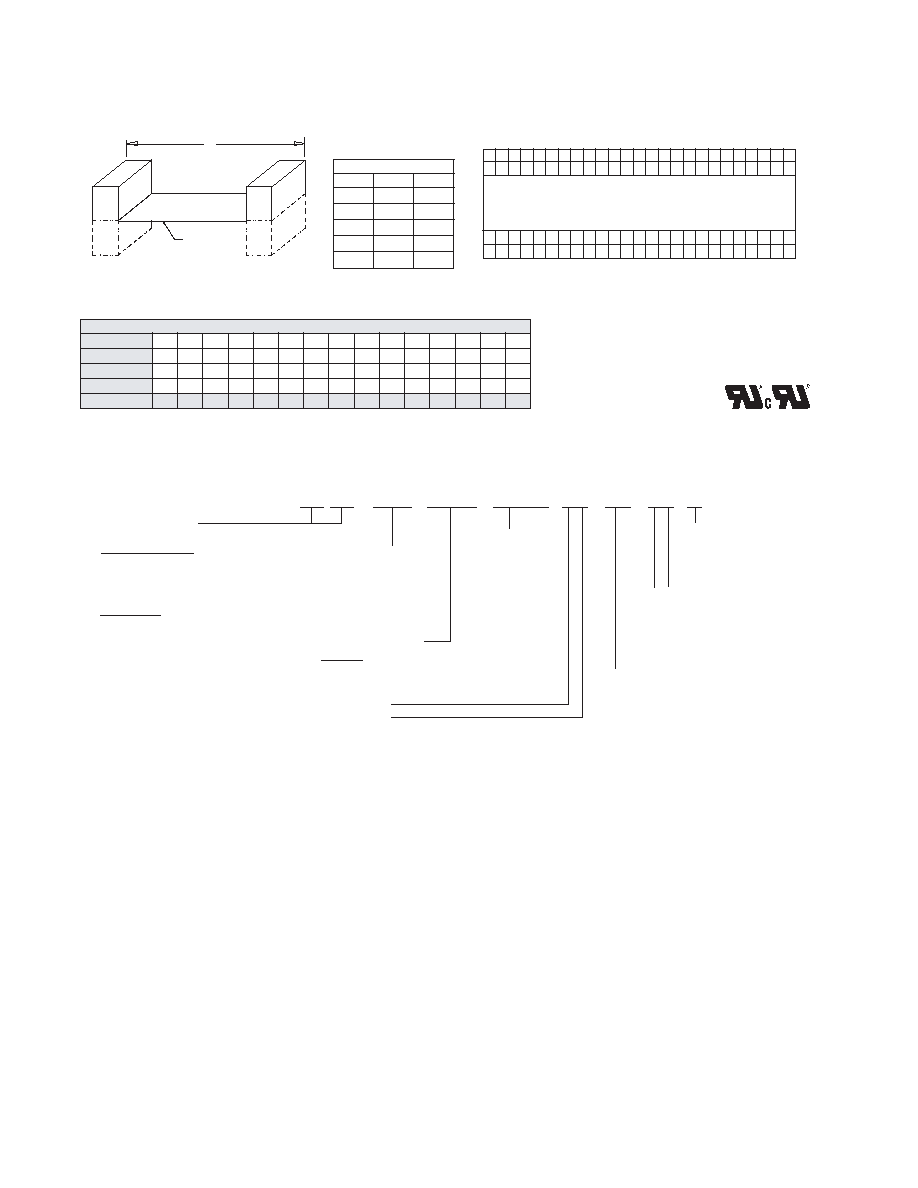
3M Molded-On Cable Assembly
2 mm x 2 mm
Length (Dim A) Tolerance
Min
Max
Tol
1.7
10.0
± 0.3
10.0
20.0
± 0.5
20.0
40.0
± 0.6
40.0
120.0
± 1.0
120.0
± 2.0
Available Options
Connector/Pos.
6
8
10
12
16
20
22
24
26
30
36
40
44
50
Socket
X
PCB
X
Cable
X
Cable / Pos.
6
8
10
12
16
20
22
24
26
30
36
40
44
50
Red Stripe
Conductor #1
(near side)
Right Connector
Left Connector
B
D
C
A
Note: A fan-out assembly, with multiple connectors on one end, requires a drawing submittal and review.
A
Connector Types
(Left and Right)
Socket, Low Profile
(.29” )
AA = no Centerbump, no Latching Ear
AB = Centerbump, no Latching Ear
AC = no Centerbump, with Latching Ear
AD = Centerbump, with Latching Ear
PCB, 2-Row
BD = Matte Sn Plating, Straight Solder Tail
Number of
Cable Conductors
Cable Product Series
28 AWG
3625 = Stranded, PVC
Assembly
Length
Tip-to-Tip
inches
(Dim A in inches)
Example:
001.7 = 1.7” Min
Connector Feature Options
0 = No Keying Required
4 = Keying Required, specifiy position(s)
Connector Orientation
Options
(Left and Right)
AB = Up-Up
AD = Up-Down
CB = Down-Up
CD = Down-Down
Centerbump Orientation
Options
0 = None
1 = Inside
2 = Outside
2M XX XX - XXX - XXXX - XXX.X - XX - XX - XX - X
Marking
0 = No Marking
1 = Label - Date Code
2 = Inkstamp - Date Code
Right
Left Right
Left
(E
Note: RIA E1 & C1 apply for all cables and connectors listed
34*
X
34
* Check for availability in late 2007.
1
Note: If “Keying” is required, mark the circuit(s) to key.
Left Connector (Odd Row)
Right Connector (Odd Row)
(Even Row)
< Red Cable Stripe
(Even Row)
1
2
49
50
Ordering Information
3M is a trademark of 3M Company.
Please recycle. Printed in USA.
3M 2007. All rights reserved.
80-4000-1955-2
3
Electronic Solutions Division
6801 River Place Blvd.
Austin, TX 78726-9000
800 225 5373
www.3M.com/interconnects
相關(guān)PDF資料 |
PDF描述 |
|---|---|
| 2MABAB-012-3625-001.7-00-AD-00-0 | INTERCONNECTION DEVICE |
| 1M6060-012-3601-001.7-00-AB-00-0 | INTERCONNECTION DEVICE |
| 1M6060-016-3601-001.7-00-AD-00-0 | INTERCONNECTION DEVICE |
| 1M6060-026-3601-001.7-00-CB-00-0 | INTERCONNECTION DEVICE |
| 1M6060-050-3601-001.7-00-AB-00-0 | INTERCONNECTION DEVICE |
相關(guān)代理商/技術(shù)參數(shù) |
參數(shù)描述 |
|---|---|
| 2M-BDBD-050-3625-003.0-00-AB-00-0 | 功能描述:電纜組件 50P 3" PCB-PCB 28AWG STRANDED PVC RoHS:否 制造商:Molex 產(chǎn)品:Power Assemblies 類型:Cable Assembly 連接器端口 A:No Connector 連接器端口 A 管腳計(jì)數(shù):4 連接器端口 B:No Connector 連接器端口 B 管腳計(jì)數(shù): 型式:Male 線規(guī) - 美國(guó)線規(guī)(AWG):20, 28 長(zhǎng)度:0.305 m 顏色:Black, Red |
| 2M-BDBD-050-3625-006.0-00-AB-00-0 | 功能描述:電纜組件 50P 6" PCB-PCB 28AWG STRANDED PVC RoHS:否 制造商:Molex 產(chǎn)品:Power Assemblies 類型:Cable Assembly 連接器端口 A:No Connector 連接器端口 A 管腳計(jì)數(shù):4 連接器端口 B:No Connector 連接器端口 B 管腳計(jì)數(shù): 型式:Male 線規(guī) - 美國(guó)線規(guī)(AWG):20, 28 長(zhǎng)度:0.305 m 顏色:Black, Red |
| 2M-BDBD-050-3625-012.0-00-AB-00-0 | 功能描述:電纜組件 50P 12" PCB-PCB 28AWG STRANDED PVC RoHS:否 制造商:Molex 產(chǎn)品:Power Assemblies 類型:Cable Assembly 連接器端口 A:No Connector 連接器端口 A 管腳計(jì)數(shù):4 連接器端口 B:No Connector 連接器端口 B 管腳計(jì)數(shù): 型式:Male 線規(guī) - 美國(guó)線規(guī)(AWG):20, 28 長(zhǎng)度:0.305 m 顏色:Black, Red |
| 2MBI100-060 | 制造商:未知廠家 制造商全稱:未知廠家 功能描述:TRANSISTOR | IGBT POWER MODULE | HALF BRIDGE | 600V V(BR)CES | 100A I(C) |
| 2MBI1000VXB-170-50 | 制造商:Fuji Electric 功能描述:IGBT DUAL 1000A 1700V MODU |
發(fā)布緊急采購(gòu),3分鐘左右您將得到回復(fù)。