- 您現(xiàn)在的位置:買賣IC網(wǎng) > PDF目錄33600 > 4060EFE (Linear Integrated Systems) Standalone Linear NiMH/NiCd Fast Battery Charger PDF資料下載
參數(shù)資料
| 型號(hào): | 4060EFE |
| 廠商: | Linear Integrated Systems |
| 英文描述: | Standalone Linear NiMH/NiCd Fast Battery Charger |
| 中文描述: | 獨(dú)立線性鎳氫/鎳鎘電池快速充電器 |
| 文件頁(yè)數(shù): | 12/20頁(yè) |
| 文件大小: | 195K |
| 代理商: | 4060EFE |
第1頁(yè)第2頁(yè)第3頁(yè)第4頁(yè)第5頁(yè)第6頁(yè)第7頁(yè)第8頁(yè)第9頁(yè)第10頁(yè)第11頁(yè)當(dāng)前第12頁(yè)第13頁(yè)第14頁(yè)第15頁(yè)第16頁(yè)第17頁(yè)第18頁(yè)第19頁(yè)第20頁(yè)

2
LTC4060
4060f
ORDER PART
NUMBER
(Note 1)
VCC to GND ............................................... –0.3V to 11V
Input Voltage
SHDN, NTC, SEL0, SEL1, PROG, ARCT,
BAT, CHEM, TIMER, PAUSE ...... –0.3V to VCC + 0.3V
Output Voltage
CHRG, ACP, DRIVE ................... –0.3V to VCC + 0.3V
Output Current (SENSE) ...................................... –2.2A
Short-Circuit Duration (DRIVE) ...................... Indefinite
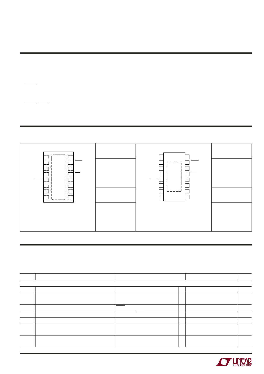
LTC4060EDHC
ABSOLUTE MAXIMUM RATINGS
W
WW
U
PACKAGE/ORDER INFORMATION
W
U
Consult LTC Marketing for parts specified with wider operating temperature ranges.
Operating Ambient Temperature Range
(Note 2) ............................................. – 40°C to 85°C
Operating Junction Temperature (Note 3) ........... 125°C
Storage Temperature Range
TSSOP Package ............................... – 65°C to 150°C
DFN Package .................................... –65°C to 125°C
Lead Temperature (Soldering, 10 sec)
TSSOP Package ................................................ 300°C
16
15
14
13
12
11
10
9
17
1
2
3
4
5
6
7
8
GND
CHRG
VCC
ACP
CHEM
NTC
SEL1
SEL0
DRIVE
BAT
SENSE
TIMER
SHDN
PAUSE
PROG
ARCT
TOP VIEW
DHC16 PACKAGE
16-LEAD (5mm × 3mm) PLASTIC DFN
TJMAX = 125°C, θJA = 37°C/W
EXPOSED PAD (PIN 17) IS GND
MUST BE SOLDERED TO PCB TO OBTAIN
θJA = 37°C/W OTHERWISE θJA = 140°C
DHC PART
MARKING
4060
ORDER PART
NUMBER
LTC4060EFE
FE PART
MARKING
4060EFE
FE PACKAGE
16-LEAD PLASTIC TSSOP
1
2
3
4
5
6
7
8
TOP VIEW
16
15
14
13
12
11
10
9
DRIVE
BAT
SENSE
TIMER
SHDN
PAUSE
PROG
ARCT
GND
CHRG
VCC
ACP
CHEM
NTC
SEL1
SEL0
17
TJMAX = 125°C, θJA = 37°C/W
EXPOSED PAD (PIN 17) IS GND
MUST BE SOLDERED TO PCB TO OBTAIN
θJA = 37°C/W OTHERWISE θJA = 135°C
The
● indicates specifications which apply over the full operating
temperature range, otherwise specifications are at TA = 25°C. VCC = 5V, VBAT = 2.8V, GND = 0V unless otherwise specified. All
currents into the device pins are positive and all currents out of the device pins are negative. All voltages are referenced to GND
unless otherwise specified.
ELECTRICAL CHARACTERISTICS
SYMBOL
PARAMETER
CONDITIONS
MIN
TYP
MAX
UNITS
VCC Supply
VCC
Operating Voltage Range (Note 4)
●
4.50
10
V
ICC
VCC Supply Current (Note 9)
IPROG = 2mA (RPROG = 698),
2.9
4.3
mA
PAUSE = VCC
ISD
VCC Supply Shutdown Current
SHDN = 0V
250
325
A
IBSD
Battery Pin Leakage Current in Shutdown (Note 5)
VBAT = 2.8V, SHDN = 0V
–1
0
1
A
IBSL
Battery Pin Leakage Current in Sleep (Note 6)
VCC = 0V, VBAT = 5.6V
–1
0
1
A
VUVI1
Undervoltage Lockout Exit Threshold
SEL0 = 0, SEL1 = 0 and SEL0 = VCC,
●
4.25
4.36
4.47
V
SEL1 = 0, VCC Increasing
VUVD1
Undervoltage Lockout Entry Threshold
SEL0 = 0, SEL1 = 0 and SEL0 = VCC,
●
4.15
4.26
4.37
V
SEL1 = 0, VCC Decreasing
相關(guān)PDF資料 |
PDF描述 |
|---|---|
| 40659 | 2.5 mm2, BRASS, RING TERMINAL |
| 40696 | 6 mm2, RING TERMINAL |
| 40696-2 | RING TERMINAL |
| 40696-1 | RING TERMINAL |
| 406C31GFREQ | QUARTZ CRYSTAL RESONATOR, 10 MHz - 50 MHz |
相關(guān)代理商/技術(shù)參數(shù) |
參數(shù)描述 |
|---|---|
| 4060-F | 制造商:Brady Corporation 功能描述: |
| 4060FI | 制造商:MALLORY 制造商全稱:MALLORY 功能描述:ELECTRIC FUEL PUMP |
| 4060-G | 制造商:Brady Corporation 功能描述: |
| 4060GB | 制造商:Greenlee Textron Inc 功能描述: |
| 4060-H | 制造商:Brady Corporation 功能描述: |
發(fā)布緊急采購(gòu),3分鐘左右您將得到回復(fù)。