- 您現(xiàn)在的位置:買賣IC網(wǎng) > PDF目錄22673 > 4064-0-18-15-03-14-10-0 (MILL-MAX MFG CORP) BERYLLIUM COPPER ALLOY, GOLD FINISH, PCB TERMINAL PDF資料下載
參數(shù)資料
| 型號: | 4064-0-18-15-03-14-10-0 |
| 廠商: | MILL-MAX MFG CORP |
| 元件分類: | 終端 |
| 英文描述: | BERYLLIUM COPPER ALLOY, GOLD FINISH, PCB TERMINAL |
| 文件頁數(shù): | 1/1頁 |
| 文件大小: | 84K |
| 代理商: | 4064-0-18-15-03-14-10-0 |
PINS
M
A HINE
D
C
PR
EC
ISI
ON
PIN RECEPTACLES
for .040” - .060” diameter pins (#03 contact)
and .059” - .063” diameter pins (#42 contact)
www.mill-max.com
516-922-6000
155
ORDER CODE: XXXX - X - 15 - XX - XX - XX -XX - 0
BASIC PART #
SPECIFY CONTACT FINISH:
SPECIFY SHELL FINISH:
01 200
" TIN/LEAD OVER NICKEL
01 200
" TIN/LEAD OVER NICKEL
14 10
" GOLD OVER NICKEL
15 10
" GOLD OVER NICKEL
27 30
" GOLD OVER NICKEL
SELECT CONTACT
#03 (DATA ON PAGE 213) or #42 CONTACT
X433-0-15-XX-03-XX-04-0
Press-fit in .106 mounting hole
0433/8433
0434-0-15-XX-03-XX-10-0
Press-fit in .106 mounting hole
0434
043X-0-15-XX-03-XX-10-0
Solder mount in .102 min.
mounting hole
0435/0436
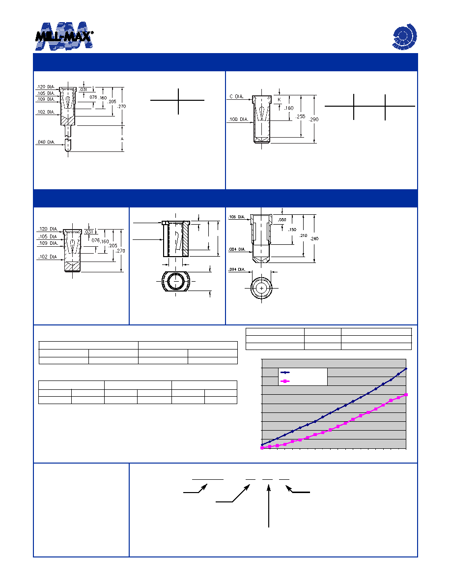
SPECIFICATIONS
SHELL MATERIAL:
Brass Alloy 360, 1/2 Hard
CONTACT MATERIAL:
Beryllium Copper Alloy 172, HT
DIMENSION IN INCHES
TOLERANCES ON:
LENGTHS:
±.005
DIAMETERS: ±.002
ANGLES:
± 2°
Basic Part
Number
Length
A
0433-0
8433-0
.120
.330
Basic Part
Number
Dia.
C
Length
K
0435-0
0436-0
.118
.125
.050
.070
0342-0-15-XX-42-XX-10-0
Hex press-fit in .090±.002
plated thru hole
0342
4064-0-18-XX-03-XX-10-0
Surface mount
4064
0342 receptacle uses
Mill-Max’s new #42 Power
Contact. This receptacle will
accept the .061±.002
power pins of brick
DC/DC converters.
#42 contact has a very low
resistance path and is rated
for currents up to 50A.
#42 contact can be ordered
in standard receptacles that
use #03 contact; or it can be
specified as the spring
element inside custom made
receptacles for power
connector applications.
Mechanical Data #42 Contact:
Insertion/Extraction Force with a .061 (nominal) pin:
Compliancy Test (the “spring back” characteristic of the contact to accept a
.059 small pin after insertion of a .063 large pin):
(Insertion/Extraction Forces are in Newtons and measured with polished
steel gage pins having elliptical shaped tips)
Electrical/Thermal Data #42 Contact:
The electrical conductivity (resistance) of #42 contact depends on the con-
ductivity of the mating pin. Tests were made with both .060 Brass (26%
IACS) and Tellurium Copper (93% IACS) pins. Temperature rise was
measured with the receptacles mounted to simulate the heatsinking of a
multilayer circuitboard.
First Cycle
2nd & Subsequent Cycles
Insertion Force
Extraction Force
Insertion Force
Extraction Force
20N
6N
10N
6N
Initial Cycle with .059 pin
Second Cycle with .063 pin
Third Cycle with .059 pin
Ins. Force
Ext. Force
Ins. Force
Ext. Force
Ins. Force
Ext. Force
18N
6N
22N
7N
3N
2N
0
2
4
6
8
10
12
14
16
18
20
5 10 152025 303540 45505560 657075 808590 95 100
Applied Current (amps)
Temperature
Rise
(°C)
#42/Brass Pin
#42/TeCu Pin
Contact/Pin combination
Resistance
Insertion Loss per pin @ 50A
#42/ Brass
.322m
.805W
#42/TeCu
.213m
.533W
Temperature Rise vs. Applied Current
相關(guān)PDF資料 |
PDF描述 |
|---|---|
| 0191640005 | 0.96 mm2, RING TERMINAL |
| 0433750001 | BRASS, TIN (20) FINISH, WIRE TERMINAL |
| 0191640006 | 0.96 mm2, RING TERMINAL |
| 0434-0-15-80-03-27-10-0 | BERYLLIUM COPPER, GOLD (30) OVER NICKEL FINISH, PCB TERMINAL |
| 0191640007 | 0.96 mm2, RING TERMINAL |
相關(guān)代理商/技術(shù)參數(shù) |
參數(shù)描述 |
|---|---|
| 4064-0-18-15-03-27-400 | 制造商:Mill-Max Mfg Corp 功能描述: |
| 4064-0-18-15-03-27-40-0 | 制造商:Mill-Max Mfg Corp 功能描述:Surface Mount 0.106 Leads Range 0.04-0.06 Standard Tail Receptacle |
| 4064-0-18-15-42-27-400 | 制造商:Mill-Max Mfg Corp 功能描述: |
| 4-0640441-0 | 制造商:TE Connectivity 功能描述: |
| 406417-1 | 制造商:TE CONNECTIVITY 功能描述: |
發(fā)布緊急采購,3分鐘左右您將得到回復(fù)。