- 您現(xiàn)在的位置:買賣IC網(wǎng) > PDF目錄156594 > 40IMX15-15-15-8K (POWER-ONE INC) 2-OUTPUT 16.8 W DC-DC REG PWR SUPPLY MODULE PDF資料下載
參數(shù)資料
| 型號: | 40IMX15-15-15-8K |
| 廠商: | POWER-ONE INC |
| 元件分類: | 電源模塊 |
| 英文描述: | 2-OUTPUT 16.8 W DC-DC REG PWR SUPPLY MODULE |
| 封裝: | 2 INCH X 1.600 INCH, 10.50 MM HEIGHT, PACKAGE-7 |
| 文件頁數(shù): | 15/20頁 |
| 文件大小: | 186K |
| 代理商: | 40IMX15-15-15-8K |

Board Mountable
DC-DC Converters
IMX/IMY 15 Series
Edition 5/06.2001
4/20
Functional Description
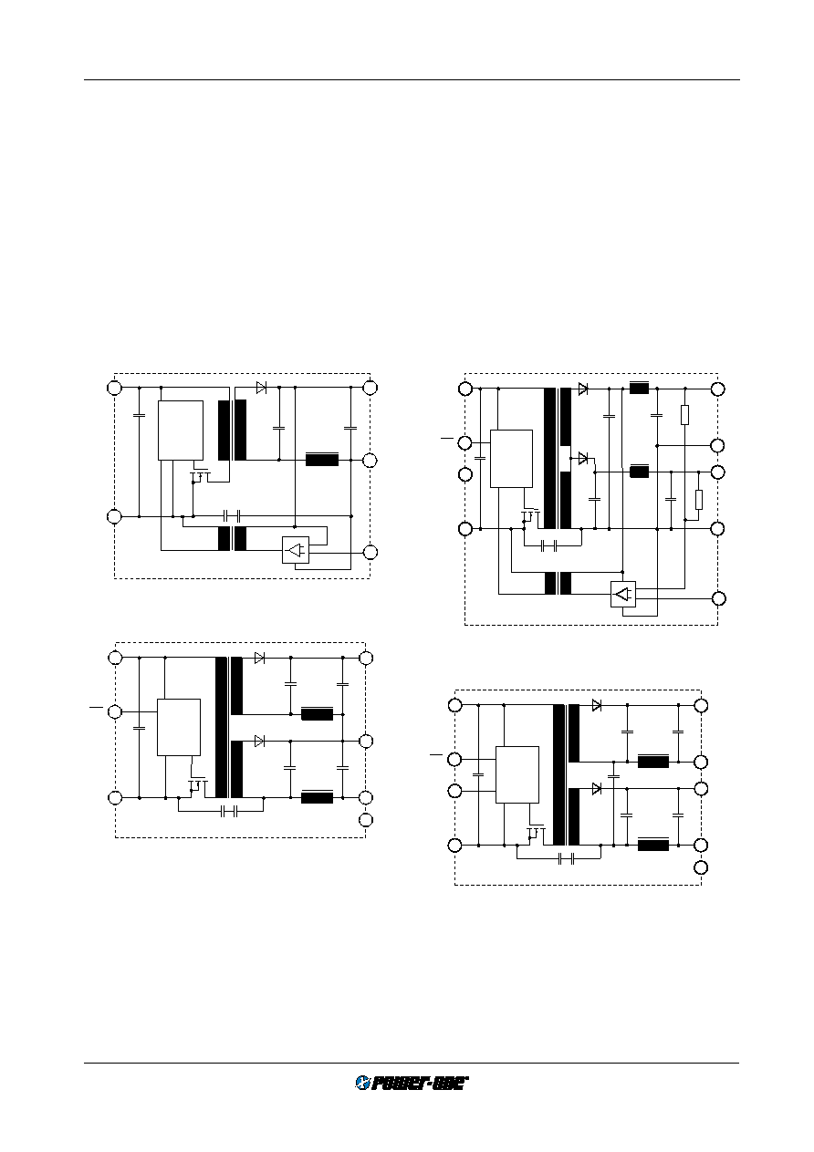
The IMX/IMY 15 series of DC-DC converters are magnetic
feed-back controlled flyback converters using current mode
PWM (Pulse Width Modulation). The -05- and -0503- output
voltage versions as well as all double output versions fitted
with option R feature an active magnetic feedback loop via
a pulse transformer which results in very tight regulation of
the output voltage (see fig.:
Block diagram, single output
types, -0503- types and double output types with option R).
The output voltages of these versions can be adjusted via
the R input. The R input is referenced to the secondary side
and allows for programming of the output voltages in the
range of approximately 80 to 105% of
Uo nom using either an
external resistor or an external voltage source.
The voltage regulation on the dual and double output ver-
sions without option R is achieved with a passive trans-
former feedback from the main transformer (see fig.:
Block
diagram, for double output types). The output voltages can
be adjusted via the Trim input. The Trim input is referenced
to the primary side of the converter and allows for program-
ming of the output voltages in the range 100 to 105% of
Uo nom by an external resistor or within 75 to 105% using an
external voltage source. The load regulation output charac-
teristic allows for paralleling of one or several double output
units with equal output voltages.
Current limitation is provided by the primary circuit, thus
limiting the total output power of double output types. The
shut down input allows remote converter on/off.
Overtemperature protection will shut down the unit in ex-
cessive overload conditions with automatic restart approxi-
mately every 50 to 60 ms.
PWM
2
× 2200 pF
1
2
4
11
15
13
Vi+
SD
Vi —
Vo+
Go
Vo—
03088
17
n.c.
PWM
2
× 2200 pF
1
2
3
4
13
15
12
11
Vi+
SD
Vi –
Vo1+
Go
n.c.
Vo2+
Go
03089
17
R
PWM
2
× 2200 pF
1500 V
1
2
3
5
Vi+
Vi–
Vo+
Vo–
03039
17 R
Fig. 1
Block diagram, single output types
Fig. 2
Block diagram, dual output types, alternative K-pinout.
Fig. 3
Block diagram, -0503- types.
PWM
2
× 2200 pF
1
2
3
4
11
12
15
13
Vi+
SD
Vi –
Vo1+
Vo1–
Trim
Vo2+
Vo2–
03090
17
n.c.
Fig. 4
Block diagram, double output types, standard pinout.
相關(guān)PDF資料 |
PDF描述 |
|---|---|
| 20IMX15-0505-8K | 2-OUTPUT 13 W DC-DC REG PWR SUPPLY MODULE |
| 40IMX15-05-9RGL | 1-OUTPUT 17.8 W DC-DC REG PWR SUPPLY MODULE |
| 40IMX15-05-8RGL | 1-OUTPUT 17.8 W DC-DC REG PWR SUPPLY MODULE |
| 40IMX15-0505-8K-G | 2-OUTPUT 14 W DC-DC REG PWR SUPPLY MODULE |
| 40IMX15-05-05-9K-G | 2-OUTPUT 14 W DC-DC REG PWR SUPPLY MODULE |
相關(guān)代理商/技術(shù)參數(shù) |
參數(shù)描述 |
|---|---|
| 40IMX-15-15-15-8R | 制造商:Power-One 功能描述:POWER SUPPLIES MISC.MELCHER PART - Bulk |
| 40IMX15-15-15-8R | 制造商:Power-One 功能描述:POWER SUPPLIES MISC.MELCHER PART - Bulk |
| 40IMX15-15-15-9 | 制造商:Power-One 功能描述: |
| 40IMX15-15-9C | 制造商:POWER-ONE 制造商全稱:Power-One 功能描述:15 Watt DC-DC Converters |
| 40IMX15-2.5-9RG | 制造商:POWER-ONE 制造商全稱:Power-One 功能描述:15 Watt DC-DC Converters |
發(fā)布緊急采購,3分鐘左右您將得到回復(fù)。