- 您現(xiàn)在的位置:買賣IC網(wǎng) > PDF目錄248240 > 42-3554-11 (ARIES ELECTRONICS INC) DIP42, IC SOCKET PDF資料下載
參數(shù)資料
| 型號: | 42-3554-11 |
| 廠商: | ARIES ELECTRONICS INC |
| 元件分類: | 插座 |
| 英文描述: | DIP42, IC SOCKET |
| 封裝: | ROHS COMPLIANT |
| 文件頁數(shù): | 1/1頁 |
| 文件大小: | 484K |
| 代理商: | 42-3554-11 |

Bristol, PA 19007-6810 USA
TEL (215) 781-9956 FAX (215) 781-9845
PRINTOUTS OF THIS DOCUMENT MAY BE OUT OF DATE AND SHOULD BE CONSIDERED UNCONTROLLED
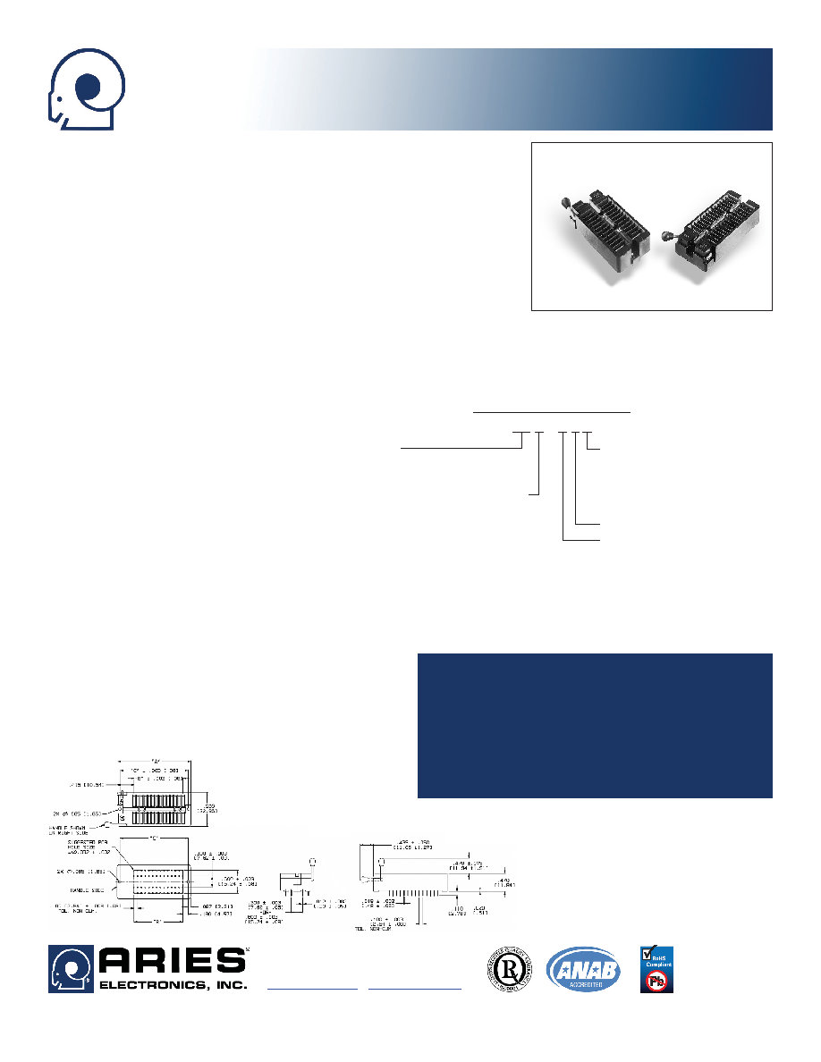
FEATURES
Aries Universal Test Socket accepts devices on 0.300 to 0.600 [7.62 to 15.24] cen-
ters.
All pin count sockets go into PCB with either 0.300 or 0.600 [7.62 to 15.24] centers.
Contacts are normally closed to eliminate dependence on plastic to sustain contact.
Socket handle can be configured with closed contacts (on) when in the UP or DOWN
position, and can be mounted on either the right or left side.
Sockets can be soldered into PCBs or plugged into any socket. Socket fits into Aries’
or any competitive test socket receptacle.
GENERAL SPECIFICATIONS
SOCKET BODY: black UL 94V-0 glass-filled Polyphenylene Sulfide (PPS)
HANDLE: Stainless Steel
HANDLE KNOB: Brass 360, 1/2-hard
CONTACTS: BeCu 172 per QQ-C-533
or BeNi 360 1/2-hard
CONTACT PLATING: 50μ [1.27μ] min. Ni under-plate per QQ-N-290, over-plated
with either 200μ [5.08μ] min. matte Sn per ASTM
B545-97 or 200μ [5.08μ] 90/10 Sn/Pb per MIL-
T-10727 or 10μ [0.254μ] min. Au per MIL-G-45204
BeNi CONTACT PLATING: 50μ [1.27μ] min. NiB
CONTACT CURRENT RATING: 1 amp
INSULATION RESISTANCE: 1000 mΩ min.
DIELECTRIC WITHSTANDING VOLTAGE: 1000 VAC
LIFE CYCLE: 25,000 to 50,000 cycles
OPERATING TEMPERATURE: -67°F [-55°C] min.;
221°F [105°C] max. for Sn plating; 302°F [150°C]
for Au plating; 392°F [200°C] for NiB plating
RETENTION FORCE (closed): 55g/pin based on a
0.020 [0.51] dia. test lead
ACCEPTS LEADS: 0.015-0.045 [0.38-1.14] wide,
0.110-0.280 [2.79-7.11] long
MOUNTING CONSIDERATIONS
See Socket Footprint below
10001
Rev. AB
Series X55X Universal Zero-Insertion-Force
DIP Test Socket
CUSTOMIZATION: In addition to the standard products shown
on this page, Aries specializes in custom design and production.
Special materials, platings, sizes, and configurations can be
furnished, depending on the quantity.
NOTE: Aries reserves the
right to change product general specifications without notice.
ALL DIMENSIONS: INCHES [MILLIMETERS]
ALL TOLERANCES: ±0.005 [0.13] UNLESS OTHERWISE SPECIFIED
“A” = (NO. OF PINS PER ROW x 0.100 [2.54]) + 0.590 [14.99]
“B” = (NO. OF PINS PER ROW -1) x 0.100 [2.54]
“C” = (NO. OF PINS PER ROW x 0.100 [2.54] + 0.415 [10.54]
CONSULT FACTORY FOR OTHER SIZES AND CONFIGURATIONS
Pins
24, 28, 32, 36,
40, 42, 44, 48
Row-to-Row Spacing (btm)
3 = 0.300 [7.62]
6 = 0.600 [15.24]
ORDERING INFORMATION
XX-X55X-1 X
Plating
0 = Sn over Ni
0TL = Sn/Pb over Ni
1 = Au over Ni
6 = NiB BeNi Contact Only
Solder Pin Tail
Handle Options
1 = Left, up is on
2 = Right, up is on
3 = Left, down is on
4 = Right, down is on (std)
NOTE: “on” = closed contacts
相關(guān)PDF資料 |
PDF描述 |
|---|---|
| 4KS101-85TG | PGA101, IC SOCKET |
| 4KS124-51TG | PGA124, IC SOCKET |
| 4KS128-04TT | PGA128, IC SOCKET |
| 44-6571-10 | DIP44, IC SOCKET |
| 415-93-268-41-003000 | SIP68, IC SOCKET |
相關(guān)代理商/技術(shù)參數(shù) |
參數(shù)描述 |
|---|---|
| 42-3554-16 | 功能描述:IC 與器件插座 DIP TEST SCKT NICKEL 40 PINS RoHS:否 制造商:Molex 產(chǎn)品:LGA Sockets 節(jié)距:1.02 mm 排數(shù): 位置/觸點(diǎn)數(shù)量:2011 觸點(diǎn)電鍍:Gold 安裝風(fēng)格:SMD/SMT 端接類型:Solder 插座/封裝類型:LGA 2011 工作溫度范圍:- 40 C to + 100 C |
| 42-3554-18 | 功能描述:IC 與器件插座 FORCE DIP TEST SCKT HIGH TEMP 42 PINS RoHS:否 制造商:Molex 產(chǎn)品:LGA Sockets 節(jié)距:1.02 mm 排數(shù): 位置/觸點(diǎn)數(shù)量:2011 觸點(diǎn)電鍍:Gold 安裝風(fēng)格:SMD/SMT 端接類型:Solder 插座/封裝類型:LGA 2011 工作溫度范圍:- 40 C to + 100 C |
| 423562 | 制造商:ERNI Electronics 功能描述:423562 |
| 42-3568-2 | 制造商:Eaton Corporation 功能描述:TRANSFORMER LIGHT ASSEMBLY |
| 42-3568-3 | 制造商:Eaton Corporation 功能描述:TRANSFORMER LIGHT ASSEMBLY |
發(fā)布緊急采購,3分鐘左右您將得到回復(fù)。