- 您現(xiàn)在的位置:買賣IC網(wǎng) > PDF目錄48172 > 42117-015 (MICROPAC INDUSTRIES INC) NEGATIVE HIGH TEMPERATURE FIXED VOLTAGE REGULATOR PDF資料下載
參數(shù)資料
| 型號(hào): | 42117-015 |
| 廠商: | MICROPAC INDUSTRIES INC |
| 元件分類: | 固定負(fù)電壓?jiǎn)温份敵鰳?biāo)準(zhǔn)穩(wěn)壓器 |
| 英文描述: | NEGATIVE HIGH TEMPERATURE FIXED VOLTAGE REGULATOR |
| 中文描述: | 15 V FIXED NEGATIVE REGULATOR, MSFM3 |
| 封裝: | ISOLATED, TO-258, 3 PIN |
| 文件頁數(shù): | 1/3頁 |
| 文件大小: | 96K |
| 代理商: | 42117-015 |
Micropac Industries cannot assume any responsibility for any circuits shown or represent that they are free from patent infringement.
Micropac reserves the right to make changes at any time in order to improve design and to supply the best product possible.
MICROPAC INDUSTRIES, INC. MICROCIRCUITS PRODUCTS DIVISION
905 E. Walnut St., Garland, TX 75040 (972) 272-3571 Fax (972) 494-2281
www.micropac.com
E-MAIL: microsales@micropac.com
2/2/05
Pg. 1 of 3
42117
NEGATIVE HIGH TEMPERATURE
FIXED VOLTAGE REGULATOR
Designed to use in high temperature environments
Mii
Features:
Operating temperature +200
°C
Output current to 1.0 A
Input voltage to –38V
Output voltage to –30 V
Internal short circuit protection, foldback and
current limiting
Isolated TO-258 package
Applications:
Down hole
Harsh environment application
DESCRIPTION
The 42117 series of fixed voltage regulators covers the output voltage range from -5 VDC through -30 VDC. These voltage
regulators are fabricated using hybrid techniques and will operate at case temperatures up to +200
°C. These devices are
complete with internal short circuit protection, which includes voltage shutdown and current foldback.
It is strongly
recommended that input and output capacitors be added as close to the case as possible. A 2f capacitor should be added
to the input and a minimum of 1.5f capacitor should be added to the output. See typical connection diagram below.
ABSOLUTE MAXIMUM RATINGS AT 200°C CASE TEMPERATURE
Output Current (IOUT)................................................................................................................................... 1.0 A
Input Voltage (VIN) ................................................................................................................................. -38 VDC
Storage Temperature (TSTG) ......................................................................................................................+250°C
Power Dissipation Pd....................................................................................................................................8 W
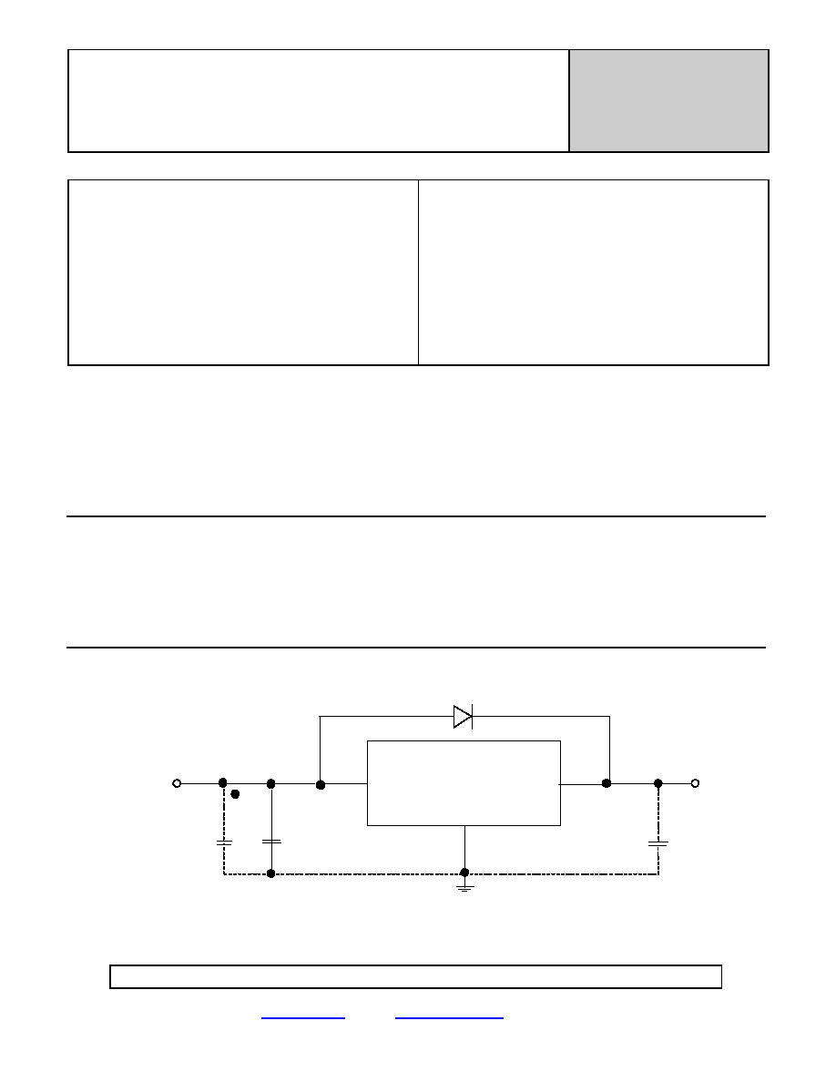
Typical Connection Diagram
Note: D1 should be installed for input safety
D1
CASE
INPUT
OUTPUT
-
COMMON
-
2uf
3
2
1.5f
RECTIFIED
VOUT
1
REGULATED
AS REQUIRED
VIN
AS REQUIRED
HEADER
MICROPAC
MICROCIRCUITS PRODUCTS
DIVISION
相關(guān)PDF資料 |
PDF描述 |
|---|---|
| 42117-018 | ** MISC CRYSTALS ** |
| 42117-024 | ** MISC CRYSTALS ** |
| 42117-030 | NEGATIVE HIGH TEMPERATURE FIXED VOLTAGE REGULATOR |
| 42117-005 | CAT5E PATCH CORD 100MHZ 7 FOOT GRAY |
| 42117 | NEGATIVE HIGH TEMPERATURE FIXED VOLTAGE REGULATOR |
相關(guān)代理商/技術(shù)參數(shù) |
參數(shù)描述 |
|---|---|
| 42117-018 | 制造商:MII 制造商全稱:MII 功能描述:NEGATIVE HIGH TEMPERATURE FIXED VOLTAGE REGULATOR |
| 42117-024 | 制造商:MII 制造商全稱:MII 功能描述:NEGATIVE HIGH TEMPERATURE FIXED VOLTAGE REGULATOR |
| 42117-030 | 制造商:MII 制造商全稱:MII 功能描述:NEGATIVE HIGH TEMPERATURE FIXED VOLTAGE REGULATOR |
| 42117-2 | 功能描述:端子 .250 FAST TAB TPBR RoHS:否 制造商:AVX 產(chǎn)品:Junction Box - Wire to Wire 系列:9826 線規(guī):26-18 接線柱/接頭大小: 絕緣: 顏色:Red 型式:Female 觸點(diǎn)電鍍:Tin over Nickel 觸點(diǎn)材料:Beryllium Copper, Phosphor Bronze 端接類型:Crimp |
| 42-117B | 制造商:Datak Corporation 功能描述: |
發(fā)布緊急采購,3分鐘左右您將得到回復(fù)。