- 您現(xiàn)在的位置:買賣IC網(wǎng) > PDF目錄30702 > 4A12P-1AH-12R5 (Bourns Inc.) Surge Line Protection Module PDF資料下載
參數(shù)資料
| 型號: | 4A12P-1AH-12R5 |
| 廠商: | Bourns Inc. |
| 英文描述: | Surge Line Protection Module |
| 中文描述: | 浪涌線路保護模塊 |
| 文件頁數(shù): | 3/3頁 |
| 文件大小: | 470K |
| 代理商: | 4A12P-1AH-12R5 |

ProSLIC is a registered trademark of Silicon Laboratories.
Specifications are subject to change without notice.
Customers should verify actual device performance in their specific applications.
COPYRIGHT 2005, BOURNS, INC. LITHO IN U.S.A. 08/05 e/LT0507
REV. 06/06
4A12P-1AH-12R5 - Surge Line Protection Module
Telcordia GR-1080-CORE Protection Coordination
Overvoltage Thyristor Selection
Protection coordination (Telcordia Technologies Generic Requirements, GR-1089-CORE, Issue 3, October 2002, section 4.6.7.1
protection coordination, page 4-15) is a new test for GR-1089-CORE issue 3 that will be a requirement on January 1, 2006. The equip-
ment using the 4A12P-1AH-12R5 overcurrent line feed resistor (LFR) must be used with either a solid state primary or a primary GDT
(5-pin gas discharge tube) such as the Bourns 2024-31-MSP Protector.
The equipment communication lines will initially be tested at the specified primary voltage protector type using a 10/1000 s generator.
A solid state primary will start testing at 400 V where a GDT primary will start at 600 V. If condition A or B defined below is not
achieved, the 10/1000 generator voltage, VG is increased (in steps of 200 V or interpolated value) to a maximum of 2000 V or until one
of the two following criteria is achieved:
A. The communication lines are stressed to 600 V peak (VP) across the equipment terminals with the GDT specified as a primary.
VP specification is reduced to 400 A for a solid state primary.
Note:Series resistance of the primary protector such as a heat coil resistance is connected between the generator and equipment.
This resistance will be effectively added to RSERIES value when calculating the generator open circuit test voltage.
B. The peak current (IPP) into the equipment terminals exceeds 100 A.
The coordination test requires ten repetitions per polarity. The communication lines will also be tested to metallic and longitudinal
procedures to ensure conformance. The equipment fails the coordination requirement if neither A or B is achieved with a maximum
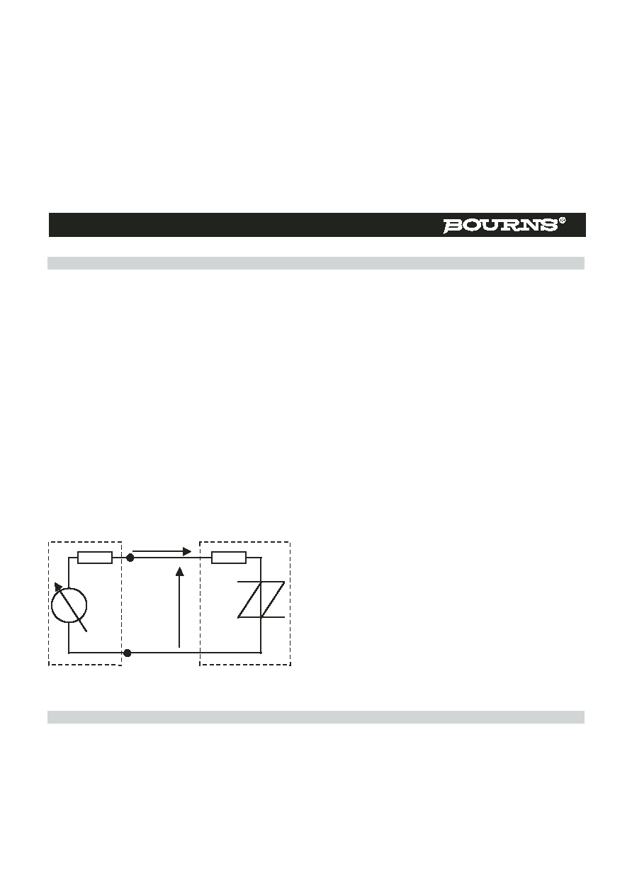
generator voltage of 2000 V or the equipment is damaged and does not operate as intended. Figure 1 shows the setup and
measurement points for the coordination test.
For example, a GDT is defined as the primary protector. The voltage, VP
will be 600 V and the current through RSERIES (4A12P-1AH-12R5) will
be 48 A (600/12.5). With a generator fictive resistance of 10 ,
the generator VG should be adjusted to 1080 V to achieve voltage
coordination. The resistance of the 4A12P-1AH-12R5 ensures the
equipment will voltage coordinate before 100A is achieved.
Note: Tolerances of the impulse generator, LFR, measurement, etc. will
provide a variation on the actual impulse generator setting.
The resistance tolerance of the LFR is ±5 % and therefore the expected maximum current from the generator will be 51 A. To ensure
reliable operation of the overvoltage protector, the thyristor should be specified to a 10/1000 s of at least 51 A.
R
G
V
G
Generator
Equipment
R
SERIES
Thyristor
P
I
P
R
G
V
G
Generator
Equipment
R
SERIES
Thyristor
V
P
I
P
Figure 1 — Coordination Requirements
相關PDF資料 |
PDF描述 |
|---|---|
| 4A12P-506-500 | Surge Line Protection Module |
| 4A12P-516-500 | Surge Line Protection Module |
| 4A4305 | Power Dividers |
| 4AA11 | Power Transistor Arrays |
| 4AA12 | Power Transistor Arrays |
相關代理商/技術參數(shù) |
參數(shù)描述 |
|---|---|
| 4A12P-1AH-12R5_11 | 制造商:BOURNS 制造商全稱:Bourns Electronic Solutions 功能描述:Surge Line Protection Module |
| 4A12P-1AH-12R5LF | 制造商:BOURNS 制造商全稱:Bourns Electronic Solutions 功能描述:Surge Line Protection Module |
| 4A12P-506-500 | 功能描述:電阻器網(wǎng)絡與陣列 12Pin 50uH SMD RoHS:否 制造商:Vishay/Thin Film 產(chǎn)品類型:Networks 電路類型:Divider 電阻器數(shù)量: 電阻數(shù)值:10 kOhms 容差:0.1 % 溫度系數(shù): 管腳數(shù)量:3 工作溫度范圍:- 55 C to + 155 C 尺寸:1.02 mm W x 3.05 mm L x 1.4 mm H 引線間隔: 端接類型:SMD/SMT 封裝:Reel |
| 4A12P-506-500_11 | 制造商:BOURNS 制造商全稱:Bourns Electronic Solutions 功能描述:Surge Line Protection Module |
| 4A12P-506-500LF | 功能描述:電阻器網(wǎng)絡與陣列 50ohm Surge Line Protection Module RoHS:否 制造商:Vishay/Thin Film 產(chǎn)品類型:Networks 電路類型:Divider 電阻器數(shù)量: 電阻數(shù)值:10 kOhms 容差:0.1 % 溫度系數(shù): 管腳數(shù)量:3 工作溫度范圍:- 55 C to + 155 C 尺寸:1.02 mm W x 3.05 mm L x 1.4 mm H 引線間隔: 端接類型:SMD/SMT 封裝:Reel |
發(fā)布緊急采購,3分鐘左右您將得到回復。