- 您現(xiàn)在的位置:買賣IC網(wǎng) > PDF目錄56705 > 508-AG8D-3 (THOMAS BETTS CORP) DIP24, IC SOCKET PDF資料下載
參數(shù)資料
| 型號(hào): | 508-AG8D-3 |
| 廠商: | THOMAS BETTS CORP |
| 元件分類: | 插座 |
| 英文描述: | DIP24, IC SOCKET |
| 文件頁數(shù): | 1/1頁 |
| 文件大?。?/td> | 76K |
| 代理商: | 508-AG8D-3 |
G
Thomas & Betts
1555 Lynnfield Road
Memphis, TN 38119
(901) 682-8221 FAX (901) 537-8805
G4
Quality & Innovation From The
Product Group
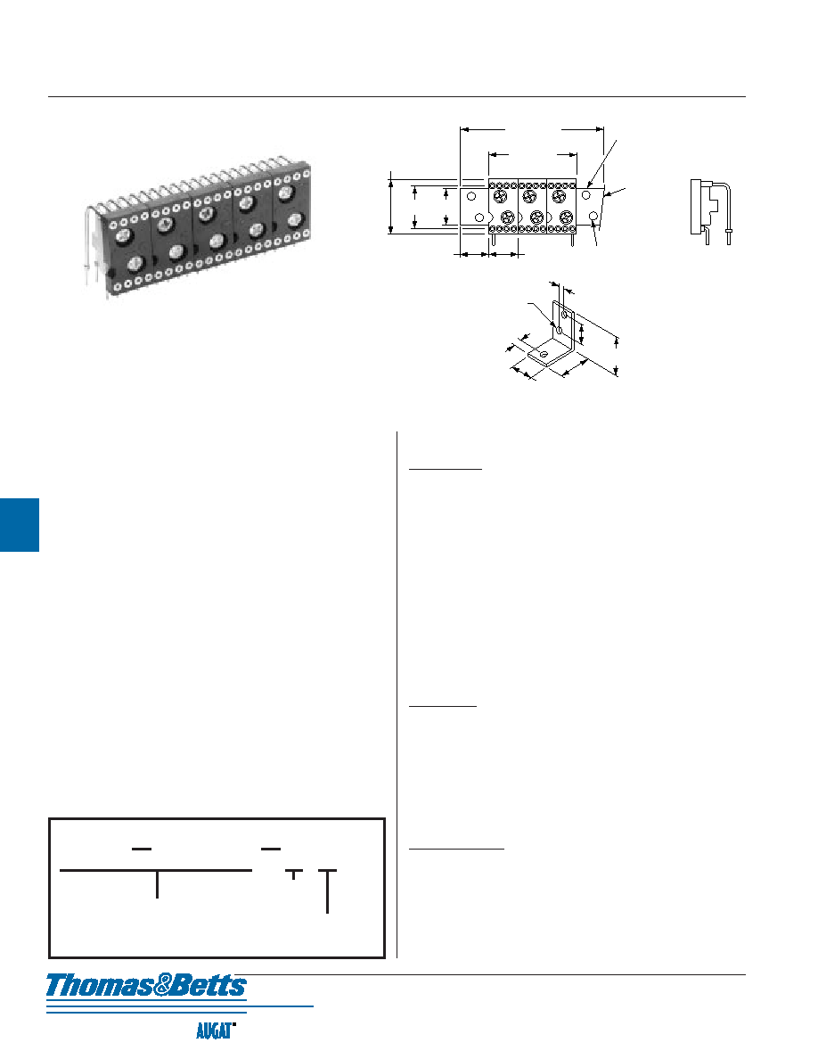
Ganged DIP Sockets
500 Series
GANGED UNIT ASSEMBLIES:
The 508 Series numbers in part block are individual sockets. Add required
dash number to appropriate socket part number for ganged unit assemblies.
With or without extrusion extension (serves as mounting ears). Units
with extrusion extensions are furnished with four No. 2 x 1/4" long self-
tapping screws.
EXTRUSION:
Extrusion for ganging also available separately, part number 508-5G1.
Simply add suffix number to indicate required length. Each extrusion is
furnished with No. 2 x 1/4" long self-tapping screws, quantity same as
number of holes in extrusion.
MOUNTING TAB:
Part number 508-4P1 is used for mounting ganged unit assemblies.
Sold separately if required.
MATERIAL SPECIFICATIONS:
Inner Contact .................. Four-fingered beryllium copper, gold
Outer Sleeve .................. Machined brass, tin/lead plated
Insulator ........................ Thermoplastic polyester UL rated 94V-0
Extrusion ........................ Vinyl
Mounting Tab ................ Stainless steel .032 (0,81) thick
3 E
5 0 8
Number
of Units
Mounting Ears
(extrusion)
Blank - No mounting ears
HOW TO ORDER
Part No. Example: 508-AG8D-3E
A G 8 D
Socket Part Number
.600
(15,24)
.500
(12,70)
.750
± .010
(19,05
± 0,25)
.400
(10,16)
Typ.
.400
(10,16)
Typ.
.076
(1,93)
Dia. Typ.
508-AG8D-3E
(with mounting ears)
508-AG8D-3
(without
mounting ears)
Extrusion
Any required
length in
multiples of
.400
(10,16)
.100
(2,54)
.093
(2,36)
Dia. Typ.
3 Places
.125
(3,18)
.270
(6,86)
.500
(12,70)
.625
(15,88)
.300
(7,62)
Mounting Tab
508-AG8D-5
PERFORMANCE SPECIFICATIONS:
MECHANICAL
Vibration ........................ Passed MIL-STD-1344, Method 2005.1,
Condition II, 10 G's
Shock .............................. Passed MIL-STD-1344, Method 2004.1,
Condition C, 100 G's
Durability ...................... Passed MIL-STD-1344, Method 2016
Normal Force ................ 200 Grams (7.0 oz.) average with .018" (0,46) dia.
polished steel pin
Insertion Force .............. 179 Grams (6.3 oz.) average with .018" (0,46) dia.
polished steel pin
Withdrawal Force .......... 63 Grams (2.2 oz.) average with .018" (0,46) dia.
polished steel pin
Solderability .................. Passed MIL-STD-202F, Method 208
Sleeve Retention
in Plastic .................... 3.0 Lbs. per line minimum PC tail
Inner Contact
Retention .................... 7.5 Lbs. per line average
ELECTRICAL
Contact Resistance ........ 10 Milliohms
Contact Rating .............. 3 Amps
Capacitance .................... 1.0 pF per MIL-STD-202, Method 305
(contact to contact)
Insulation Resistance .... 5,000 Megohms min. @ 500 VDC per
MIL-STD-1344, Method 3003.1
Dielectric Withstanding
Voltage ...................... 1,000 Volts RMS per MIL-STD-1344,
Method 3001.1
ENVIRONMENTAL
Humidity ........................ Passed MIL-STD-1344, Method 1002.2, Cond. II
Thermal Shock .............. Passed MIL-STD-1344, Method 1003.1, Cond. A
Operation Temperature .. Gold inner contact -55
°C to +125°C
Tin/lead inner contact -55
°C to +105°C
相關(guān)PDF資料 |
PDF描述 |
|---|---|
| 508-AG8D-3E | DIP24, IC SOCKET |
| 508-AG8D-5 | DIP40, IC SOCKET |
| 50AC5T15 | 3-OUTPUT 45 W AC-DC REG PWR SUPPLY MODULE |
| 50AC5D | 2-OUTPUT 45 W AC-DC REG PWR SUPPLY MODULE |
| 50AC28S | 1-OUTPUT 55 W AC-DC REG PWR SUPPLY MODULE |
相關(guān)代理商/技術(shù)參數(shù) |
參數(shù)描述 |
|---|---|
| 508-AG8D-3E | 制造商:TE Connectivity 功能描述: |
| 50-8B/H17 | 功能描述:電容硬件 50-8B WSHR & NUT RoHS:否 制造商:Cornell Dubilier 系列: 產(chǎn)品: 封裝: |
| 508B-1 | 制造商:Newport Electronics Inc 功能描述:4-20MA LCD DISPLAY PANEL |
| 508B-2 | 制造商:Newport Electronics Inc 功能描述:LOOP POWERED METER, No. of Digits / Alpha:3-1/2, Meter Function:Current Loop Indicator, Meter Range:1mA to 5mA / 4mA to 20mA / 10mA to 50mA, Digit Height:8.9mm, Supply Voltage Range:-, Operating Temperature Min:-40C , RoHS Compliant: NA |
| 508C697G38 | 制造商:NGC 功能描述: |
發(fā)布緊急采購,3分鐘左右您將得到回復(fù)。