- 您現(xiàn)在的位置:買賣IC網(wǎng) > PDF目錄298399 > 56P30-01-1-06S (GRAYHILL INC) ROTARY SWITCH-6POSITIONS, SP6T, LATCHED, 0.2A, 30VDC, THROUGH HOLE-STRAIGHT PDF資料下載
參數(shù)資料
| 型號: | 56P30-01-1-06S |
| 廠商: | GRAYHILL INC |
| 元件分類: | 開關 |
| 英文描述: | ROTARY SWITCH-6POSITIONS, SP6T, LATCHED, 0.2A, 30VDC, THROUGH HOLE-STRAIGHT |
| 封裝: | ROHS COMPLIANT |
| 文件頁數(shù): | 2/4頁 |
| 文件大小: | 144K |
| 代理商: | 56P30-01-1-06S |

Grayhill, Inc. 561 Hillgrove Avenue LaGrange, Illinois
60525-5997 USA Phone: 708-354-1040 Fax: 708-354-2820 www.grayhill.com
Rotary
Switches
Single Deck Rotary Switches
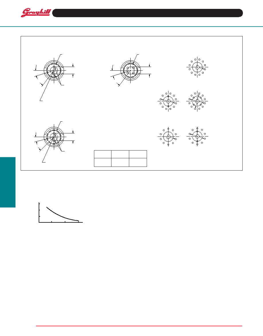
CirCuit Diagrams anD rear Views: PC mountable anD solder Lug terminals
rear View
Circuit as Viewed From shaft end
30° angle
of throw
One POLe
twO POLes
36° angle
of throw
PC mount
solder Lug
Dimension
terminals
a
.184 ± .015
.126 ± .015
(4,67 ± 0,38)
(3,20 ± 0,38)
FOur POLes
One POLe
twO POLes
15°
30° TYP.
.366 ± .015
(9,30 ± 0,38)
DIA. CIRCLE
OF CENTERS
.190 ± .015 (4,83 ± 0,38)
DIA. CIRCLE OF CENTERS
(PC MOUNT AND
SOLDER LUG)
COMMON LOCATION
FOR 1 POLE SWITCH
COMMON LOCATION
FOR 2 POLE SWITCH
POS. 1
COMMON LOCATION
FOR 1 POLE SWITCH
18°
36° TYP.
DIMENSION A
DIA. CIRCLE OF CENTERS
.340 ± .015
(8,64 ± 0,38) DIA.
CIRCLE OF CENTERS
COMMON LOCATION
FOR 2 POLE SWITCH
POS. 1
15°
30° TYP.
.366 ± .015
(9,30 ± 0,38)
DIA. CIRCLE
OF CENTERS
.190 ± .015 (4,83 ± 0,38)
DIA. CIRCLE OF CENTERS
(PC MOUNT AND
SOLDER LUG)
POS. 1
7
8
9
10
11
12
1
2
3
4
5
6
C2
C1
6
7
8
9
10
1
2
3
4
5
7
8
9
10
11
12
1
2
3
4
5
6
7
8
9
10
11
12
1
2
3
4
5
6
C3
C4
C2
C1
C2
C1
6
7
8
9
10
1
2
3
4
5
SPECIFICATIONS
Electrical Ratings
Chart shown for non-shorting (break before make)
contacts, resistive load.
300
200
0
10
20
30
CYCLES x 1000
115 Vac 0r 30 Vdc
CURRENT
-
MILLIAMPS
100
Onecycleis360°rotationclockwiseand360°return.
the data for the curve was measured at sea level,
25°Cand68%relativehumiditywiththelifelimiting
criteria which follows.
Contact Resistance: 100 milliohms maximum,
(15 milliohms initially).
Insulation Resistance: 10,000 mohms
minimumbetweenmutuallyinsulatedparts(50,000
mohms initially).
Voltage Breakdown: 600 Vac minimum
between mutually insulated parts at standard
atmospheric pressure.
Life Expectancy: as determined from the load-
life curve for the current to be switched. Contact
graYHiLLformoreinformationifanyofthefollowing
is true: the life limiting criteria are more critical than
those listed; longer operation is required; a larger
make and break current is required; the operating
environment includes elevated temperatures or
reduced pressures.
Contact Carry Rating: switch will carry 6
amperes continuously with a maximum
contact temperature rise of 20°C.
Additional Characteristics
Contact Type and Forces: shorting or non-
shorting wiping contacts with over 25 grams of
contact force.
Shaft Flat Orientation: Flat opposite contacting
position of pole number one (see circuit
diagrams).
Terminals: switches have the full circle of
terminals, regardless of number of active
positions.
Stop Strength: 7.5 lb-in. minimum
Rotational Torque: 3.5 to 9 oz-in. (21-53
mn-m), depending on the number of poles.
Bushing Mounting: required for switches with
stops, and recommended for switches without
stops.
Meets MIL-S-3786 for:
High and medium shock;Vibration (10 to 2,000 Hz);
thermal shock (-65° to 85 ° C); salt spray; explosion;
stop strength (7.5 in-lbs. minimum (.85 n-m);
terminal strength; sealed styles withstand water
pressure of 15 Psi minimum (103 KPa) without
leakage.
Materials and Finishes
Housing: Zinc die cast, tin zinc plated
Mounting Nut: Brass, tin zinc plated
Lockwasher: spring steel, zinc plated
Panel Seal: silicone rubber
Shaft and Stop Arm: Zinc die cast
Retaining Ring: 302 stainless steel, passivated
Shaft Seal: silicone rubber
Stop Pins: 303 stainless steel, passivated
Detent Rotor: molded thermoplastic
Detent Spring: tinned music wire
Detent Balls: steel, nickel-plated
Contact Spring: stainless steel, passivated
Rotor Contact:
non-shorting: Brass, silver over nickel plate
shorting: Zinc, silver over nickel over copper
plate
Common Ring: Brass, gold over silver over
nickel plate
Terminals: Brass, gold over silver over nickel
plate
rotary
12
相關PDF資料 |
PDF描述 |
|---|---|
| 56F627-019-GBL | 44 CONTACT(S), MALE, D SUBMINIATURE CONNECTOR, SOLDER |
| 56-643-018-GBL | 78 CONTACT(S), FEMALE, D SUBMINIATURE CONNECTOR, SOLDER |
| 56F627-019-LI | 44 CONTACT(S), MALE, D SUBMINIATURE CONNECTOR, SOLDER |
| 56F627-019-S | 44 CONTACT(S), MALE, D SUBMINIATURE CONNECTOR, SOLDER |
| 56F627-020-50G | 44 CONTACT(S), MALE, D SUBMINIATURE CONNECTOR, SOLDER |
相關代理商/技術參數(shù) |
參數(shù)描述 |
|---|---|
| 56P30-01-1-07N | 制造商:Grayhill 功能描述:SWIT ROTARY SP 7 SHAFT PC PINS 0.2A 115VAC 30VDC - Bulk 制造商:Grayhill 功能描述:SWITCH ROTARY SP7T 制造商:Grayhill 功能描述:Switch Rotary SP7T 7 Flatted Shaft PC Pins 0.2A 115VAC 30VDC |
| 56P30-01-1-07S | 制造商:Grayhill 功能描述:SWIT ROTARY SP 7 SHAFT PC PINS 0.2A 115VAC 30VDC - Bulk 制造商:Grayhill 功能描述:SWITCH ROTARY SP7T 制造商:Grayhill 功能描述:Switch Rotary SP7T 7 Flatted Shaft PC Pins 0.2A 115VAC 30VDC |
| 56P30-01-1-08N | 制造商:Grayhill 功能描述:SWIT ROTARY SP 8 SHAFT PC PINS 0.2A 115VAC 30VDC - Bulk 制造商:Grayhill 功能描述:SWITCH ROTARY SP8T 制造商:Grayhill 功能描述:Switch Rotary SP8T 8 Flatted Shaft PC Pins 0.2A 115VAC 30VDC |
| 56P30-01-1-08S | 制造商:Grayhill 功能描述:SWIT ROTARY SP 8 SHAFT PC PINS 0.2A 115VAC 30VDC - Bulk 制造商:Grayhill 功能描述:SWITCH ROTARY SP8T 制造商:Grayhill 功能描述:Switch Rotary SP8T 8 Flatted Shaft PC Pins 0.2A 115VAC 30VDC |
| 56P30-01-1-10N | 制造商:Grayhill 功能描述:SWIT ROTARY SP 10 SHAFT PC PINS 0.2A 115VAC 30VDC - Bulk 制造商:Grayhill 功能描述:SWITCH ROTARY SP10T 制造商:Grayhill 功能描述:Switch Rotary SP10T 10 Flatted Shaft PC Pins 0.2A 115VAC 30VDC |
發(fā)布緊急采購,3分鐘左右您將得到回復。