- 您現(xiàn)在的位置:買賣IC網(wǎng) > PDF目錄67328 > 5962-8967901XX (MAXIM INTEGRATED PRODUCTS INC) 1-CH 12-BIT SUCCESSIVE APPROXIMATION ADC, SERIAL/PARALLEL ACCESS, CQCC44 PDF資料下載
參數(shù)資料
| 型號: | 5962-8967901XX |
| 廠商: | MAXIM INTEGRATED PRODUCTS INC |
| 元件分類: | ADC |
| 英文描述: | 1-CH 12-BIT SUCCESSIVE APPROXIMATION ADC, SERIAL/PARALLEL ACCESS, CQCC44 |
| 封裝: | CERAMIC, LCC-44 |
| 文件頁數(shù): | 12/13頁 |
| 文件大?。?/td> | 403K |
| 代理商: | 5962-8967901XX |
MAX5820
The MAX5820 SDA and SCL drivers are open-drain out-
puts, requiring a pullup resistor to generate a logic high
voltage (see the Typical Operating Circuit ). Series
resistors RS are optional. These series resistors protect
the input stages of the MAX5820 from high-voltage
spikes on the bus lines, and minimize crosstalk and
undershoot of the bus signals.
Bit Transfer
One data bit is transferred during each SCL clock
cycle. The data on SDA must remain stable during the
high period of the SCL clock pulse. Changes in SDA
while SCL is high are control signals (see the START
and STOP Conditions section). Both SDA and SCL idle
high when the I2C bus is not busy.
START and STOP Conditions
When the serial interface is inactive, SDA and SCL idle
high. A master device initiates communication by issu-
ing a START condition. A START condition is a high-to-
low transition on SDA with SCL high. A STOP condition
is a low-to-high transition on SDA, while SCL is high
(Figure 2). A START condition from the master signals
the beginning of a transmission to the MAX5820. The
master terminates transmission by issuing a not
acknowledge followed by a STOP condition (see the
Acknowledge Bit (ACK) section). The STOP condition
frees the bus. If a repeated START condition (Sr) is
generated instead of a STOP condition, the bus
remains active. When a STOP condition or incorrect
address is detected, the MAX5820 internally discon-
nects SCL from the serial interface until the next START
condition, minimizing digital noise and feedthrough.
Early STOP Conditions
The MAX5820 recognizes a STOP condition at any
point during transmission except if a STOP condition
occurs in the same high pulse as a START condition
(Figure 3). This condition is not a legal I2C format; at
least one clock pulse must separate any START and
STOP conditions.
Repeated START Conditions
A repeated START (Sr) condition may indicate a
change of data direction on the bus. Such a change
occurs when a command word is required to initiate a
read operation. Sr may also be used when the bus
master is writing to several I2C devices and does not
want to relinquish control of the bus. The MAX5820 seri-
al interface supports continuous write operations with or
without an Sr condition separating them. Continuous
read operations require Sr conditions because of the
change in direction of data flow.
Dual, 8-Bit, Low-Power, 2-Wire, Serial
Voltage-Output DAC
8
_______________________________________________________________________________________
POWER-DOWN
COMMAND BITS
PD1
PD0
MODE/FUNCTION
00
Power-up device. DAC output
restored to previous value.
01
Power-down mode 0. Power down
device with output floating.
10
Power-down mode 1. Power down
device with output terminated with
1k
to GND.
11
Power-down mode 2. Power down
device with output terminated with
100k
to GND.
Table 1. Power-Down Command Bits
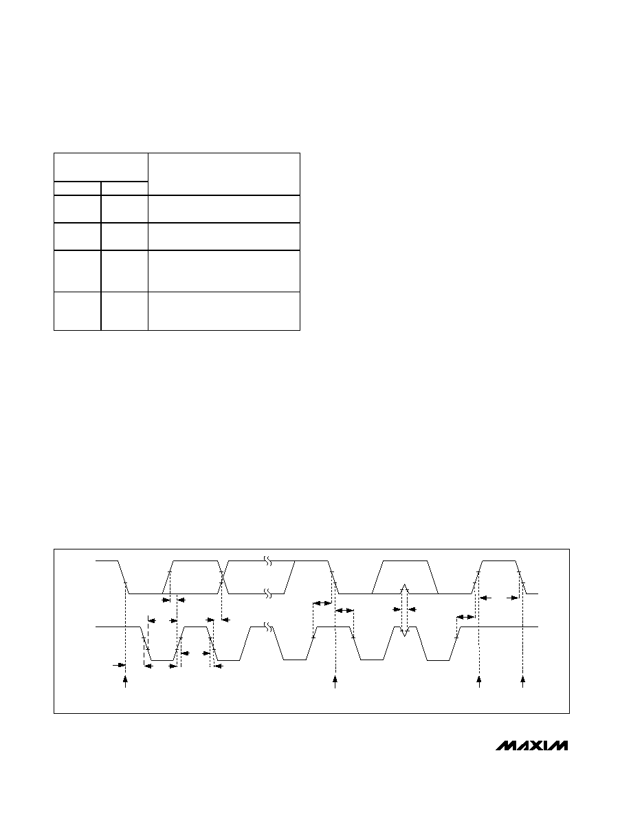
SCL
SDA
STOP
CONDITION
START
CONDITION
REPEATED START CONDITION
START CONDITION
tLOW
tSU, DAT
tSU, STA
tSP
tBUF
tHD, STA
tSU, STO
tF
tHD, STA
tHIGH
tHD, DAT
tR
Figure 1. 2-Wire Serial-Interface Timing Diagram
相關PDF資料 |
PDF描述 |
|---|---|
| 5962-8968303HZA | 1-OUTPUT 15 W DC-DC REG PWR SUPPLY MODULE |
| 5962-9158001HZA | 1-OUTPUT 20 W DC-DC REG PWR SUPPLY MODULE |
| 5962-9162501HZA | 1-OUTPUT 20 W DC-DC REG PWR SUPPLY MODULE |
| 5962-8968301HXA | 1-OUTPUT 15 W DC-DC REG PWR SUPPLY MODULE |
| 5962-8968301HXA | 1-OUTPUT 15 W DC-DC REG PWR SUPPLY MODULE |
相關代理商/技術(shù)參數(shù) |
參數(shù)描述 |
|---|---|
| 5962-89680012A | 制造商:Texas Instruments 功能描述:Octal Transmitter/Receiver 20-Pin LCCC Tube |
| 5962-89680012A-T | 制造商:Rochester Electronics LLC 功能描述:- Tape and Reel |
| 5962-8968001RA | 制造商:Texas Instruments 功能描述:Octal Transmitter/Receiver 20-Pin CDIP Tube 制造商:Texas Instruments 功能描述:LINE TRNSCVR 8TR 8TX 8RX 20CDIP - Rail/Tube |
| 5962-8968001SA | 制造商:Texas Instruments 功能描述:Octal Transmitter/Receiver 20-Pin CFPAK Tube 制造商:Rochester Electronics LLC 功能描述:- Bulk |
| 5962-89681012A | 制造商:Rochester Electronics LLC 功能描述: 制造商:Texas Instruments 功能描述:55ALS161, AVAIL AS SMD ONLY, RERELEASE - Rail/Tube 制造商:Texas Instruments 功能描述:Octal Transmitter/Receiver IEEE-488 20-Pin LCCC Tube |
發(fā)布緊急采購,3分鐘左右您將得到回復。