- 您現(xiàn)在的位置:買賣IC網(wǎng) > PDF目錄91414 > 5962-9083801HYX DUAL OP-AMP, 1000 uV OFFSET-MAX, MDIP12 PDF資料下載
參數(shù)資料
| 型號(hào): | 5962-9083801HYX |
| 元件分類: | 運(yùn)算放大器 |
| 英文描述: | DUAL OP-AMP, 1000 uV OFFSET-MAX, MDIP12 |
| 文件頁(yè)數(shù): | 2/4頁(yè) |
| 文件大小: | 56K |
| 代理商: | 5962-9083801HYX |

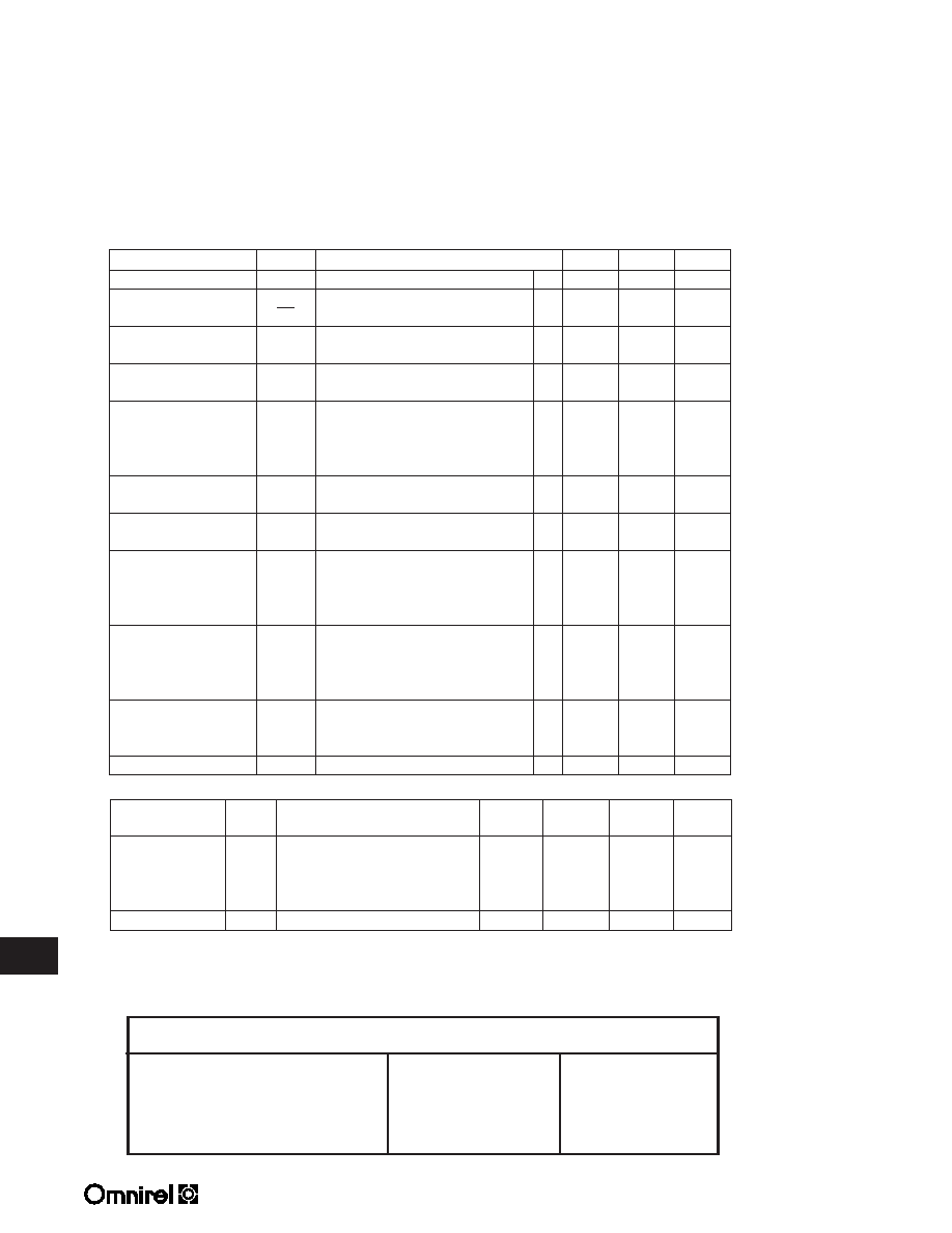
3.4 - 6
3.4
OMA2541SKB OMA2541SKCB OMA2541SDB
Parameter
Symbol
Conditions
Min.
Max.
Units
Input Offset Voltage
V
IO
T
A = +25°C
-1
+1
mV
Input Offset
Voltage Drift
T
A
= -55°C and +125°C
-30
+30
V/°C
Input Bias Current
±I
B
-50
+50
pA
-50
+50
nA
Input Offset Current
I
OS
-30
+30
pA
-20
+20
nA
Power Supply
+PSRR
-V
CC = -34VDC, +VCC = +10 to +40VDC
-10
+10
V/V
Rejection Ratio
-20
+20
-PSRR
+V
CC = +34VDC, -VCC = -10 to -40VDC
-10
+10
V/V
-20
+20
Common Mode
CMRR
V
CM = +22VDC, f = DC
95
dB
Rejection Ratio
90
Supply Currents
±I
CC
V
CM = 0V,
-60
+60
mA
no load condition, total supply current
Output Voltage Peak
V
OP
I
O = 5A peak, RL = 5.6 ,
±28.6
V
10 kHz sine wave, T
A = 25°C
R
L = 10 , 10 kHz sine wave
±30
V
A = -55°C and +125°C
Output Current Peak
I
OP
R
L = 5.6 , VOUT = ±30VDC,±5
A
T
A = 25°C
(2)
R
L = 10k , VOUT = ±30VDC
±3
A
T
A = -55°C and +125°C
(2)
Voltage Gain
A
VS
R
L = 10k
T
A = 25°C
95
dB
T
A = 125°C
90
T
A = -55°C
85
Slew Rate
±SR
R
L = 6.5 , TA = +25°C
±6
V/s
ELECTRICAL CHARACTERISTICS (-55°C T
A
+125°C; V
CC = ±37VDC
(1)
V
IO
T
Part Number Designator
Standard Military Drawing Number
Omnirel Part Number
Package
5962-9083801HXX
OMA2541SKB
TO-3
5962-9083802HXX
OMA2541SKCB
TO-3 Copper Slug
5962-9083801HYX
OMA2541SDB
12 Pin DIP
Thermal Resistance
Standard
Copper Slug
Power
Maximum
Conditions
TO-3
DIP
Units
Junction-to-Case
q
JC
Both Amplifiers(3), AC Output f > 60Hz
1.0
.8
.65
°C/W
Both Amplifiers(3), DC Output
1.2
1.0
.8
°C/W
One Amplifier, AC Output f > 60Hz
1.5
1.2
1.0
°C/W
One Amplifier, DC Output
1.9
1.5
1.15
°C/W
Junction-to-Ambient
q
JA
No Heat Sink
30
°C/W
NOTES: (1) Unless otherwise specified, these tests are for each amplifier.
(2) Internal current limit circuitry is controlled by a single external resistor, R
CL. To calculate the value of the current limit
resistor, use R
CL = (0.809/ILIM) - 0.057, where ILIM is equal to the desired output current (IOP).
(3) Assumes equal dissipation in both amplifiers.
Denotes over specified temperature range.
相關(guān)PDF資料 |
PDF描述 |
|---|---|
| 5962-9083802HXX | DUAL OP-AMP, 1000 uV OFFSET-MAX, MBFM12 |
| 5962-9086802MPX | OP-AMP, 2200 uV OFFSET-MAX, CDIP8 |
| 5962-9086801MXX | OP-AMP, 570 MHz BAND WIDTH, CDSO8 |
| 5962-9086801MPX | OP-AMP, 2200 uV OFFSET-MAX, CDIP8 |
| 5962-9086802MXX | OP-AMP, 570 MHz BAND WIDTH, CDSO8 |
相關(guān)代理商/技術(shù)參數(shù) |
參數(shù)描述 |
|---|---|
| 5962-9084101MCA | 制造商:Linear Technology 功能描述:POWER SUPPLY-VOLTAGE REGULATOR |
| 5962-9084501MPA | 制造商:Rochester Electronics LLC 功能描述:- Bulk |
| 5962-9084701MRA | 制造商:Micross Components, Inc. 功能描述:DRAM, 4MB - Rail/Tube |
| 59629084701MTA | 制造商:ASI 功能描述:MT4C4001JECN-12 |
| 5962-9084701MTA | 制造商:Micross Components, Inc. 功能描述:DRAM, 4MB - Trays |
發(fā)布緊急采購(gòu),3分鐘左右您將得到回復(fù)。