- 您現(xiàn)在的位置:買賣IC網(wǎng) > PDF目錄382812 > 73K224L-IP (TDK Corporation) V.22bis/V.22/V.21/ Bell 212A/Bell 103 Single-Chip Modem PDF資料下載
參數(shù)資料
| 型號: | 73K224L-IP |
| 廠商: | TDK Corporation |
| 英文描述: | V.22bis/V.22/V.21/ Bell 212A/Bell 103 Single-Chip Modem |
| 中文描述: | V.22bis/V.22/V.21 /貝爾212A/Bell 103單芯片調制解調器 |
| 文件頁數(shù): | 25/32頁 |
| 文件大小: | 206K |
| 代理商: | 73K224L-IP |
第1頁第2頁第3頁第4頁第5頁第6頁第7頁第8頁第9頁第10頁第11頁第12頁第13頁第14頁第15頁第16頁第17頁第18頁第19頁第20頁第21頁第22頁第23頁第24頁當前第25頁第26頁第27頁第28頁第29頁第30頁第31頁第32頁

73K224L
V.22bis/V.22/V.21/Bell 212A/Bell 103
Single-Chip Modem
25
APPLICATIONS INFORMATION
GENERAL CONSIDERATIONS
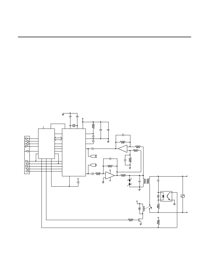
Figures 1 and 2 show basic circuit diagrams for
K-Series modem integrated circuits. K-Series products
are designed to be used in conjunction with a control
processor, a UART or RS-232 serial data interface,
and a DAA phone line interface to function as a typical
intelligent modem. The K-Series ICs interface directly
with Intel 8048 and 80C51 microprocessors for control
and status monitoring purposes. Two typical DAA
arrangements are shown: one for a split ±5 or
±12V design and one for a single 5V design. These
diagrams are for reference only and do not represent
production-ready modem designs.
K-Series devices are available with two control
interface versions: one for a parallel multiplexed
address/data interface, and one for a serial
interface. The parallel version is intended for use
with 8039/48 or 8031/51 microcontrollers from
Intel or many other manufacturers. The serial
interface can be used with other microcontrollers
or in applications where only a limited number of
port lines are available or the application does not
lend itself to a multiplexed address/data interface.
The parallel versions may also be used in the
serial mode, as explained in the data sheet pin
description.
In most applications the controller will monitor the
serial data for commands from the DTE and the
received data for break signals from the far end
modem. In this way, commands to the modem are
sent over the same line as the transmitted data. In
other applications the RS-232 interface handshake
lines are used for modem control.
FIGURE 1: Basic Box Modem with Dual-Supply Hybrid
RS232
LEVEL
CONVERTERS
CA
CB
CC
CD
CF
RTS
CTS
DSR
DTR
DCD
P1.0
P1.1
P1.2
P1.3
P1.5
P1.6
P1.7
P3.0
RESET
TXD
RXD
EXCLK
RXCLK
TXCLK
BA
BB
DA
DD
DB
U5, U6
MC145406
RD
WR
ALE
P3.1
P3.2
P0.0-7
INT
XTL2
XTL1
N/C
80C51
XTL1
INT
XTL2
ISET
GND
RD
WR
ALE
CS
VREF
RXA
CLK
VDD
Y1
1MHZ
C14
39 pF
C13
18 pF
R10
+5V
C10
0.1 μF
C11
0.1 μF
C9
0.1 μF
C8
22 μF
+
RESET
C12
1 μF
+5V
TXA
C6
0.1 μF
RXA
LM 1458
-
+
3R5
C1
390 pF
R4
R4
20K
C7
0.1 μF
TXA
R6
20K
475 1%
0.4C5
250V
D1
IN4004
R8
22K
MIT1
671-8005
VR1
V250L20
T
R
U2
4N35
+5V
K1
D2
IN914
2N2222A
Q1
R9
10K
U1A
R3
3.6K
C3
1000 pF
V+
R7
43.2K
30C2
LM 1458
+
U1B
V–
C4
0.033 μF
R1
4.7V
ZENER
K-SERIES
LOW
POWER
FAMILY
22K
+5
相關PDF資料 |
PDF描述 |
|---|---|
| 73K321L-IH | CCITT V.23, V.21 Single-Chip Modem |
| 73K321L-IP | CCITT V.23, V.21 Single-Chip Modem |
| 73K321L | Miniature Switch, High Precision |
| 73K322L-IH | CCITT V.23, V.22, V.21 Single-Chip Modem |
| 73K322L-IP | CCITT V.23, V.22, V.21 Single-Chip Modem |
相關代理商/技術參數(shù) |
參數(shù)描述 |
|---|---|
| 73K224L-IP/F | 功能描述:電信集成電路 RoHS:否 制造商:STMicroelectronics 類型:Telecom IC - Various 工作電源電壓:4.75 V to 5.25 V 電源電流: 工作溫度范圍:- 40 C to + 85 C 安裝風格:SMD/SMT 封裝 / 箱體:PQFP-100 封裝:Tray |
| 73K244L-IP | 制造商:TDK 功能描述:Single Chip Modem |
| 73K302L | 制造商:TDK 制造商全稱:TDK Electronics 功能描述:Single-Chip Modem |
| 73K302L-IH | 制造商:TDK 制造商全稱:TDK Electronics 功能描述:Single-Chip Modem |
| 73K302L-IP | 制造商:TDK 制造商全稱:TDK Electronics 功能描述:Single-Chip Modem |
發(fā)布緊急采購,3分鐘左右您將得到回復。