- 您現(xiàn)在的位置:買賣IC網(wǎng) > PDF目錄158852 > 74S140 (Fairchild Semiconductor Corporation) Dual 4-Input NAND 50з Line Driver PDF資料下載
參數(shù)資料
| 型號(hào): | 74S140 |
| 廠商: | Fairchild Semiconductor Corporation |
| 英文描述: | Dual 4-Input NAND 50з Line Driver |
| 中文描述: | 雙4輸入與非50з線驅(qū)動(dòng)器 |
| 文件頁(yè)數(shù): | 2/3頁(yè) |
| 文件大小: | 35K |
| 代理商: | 74S140 |
www.fairchildsemi.com
2
D
M
74S140
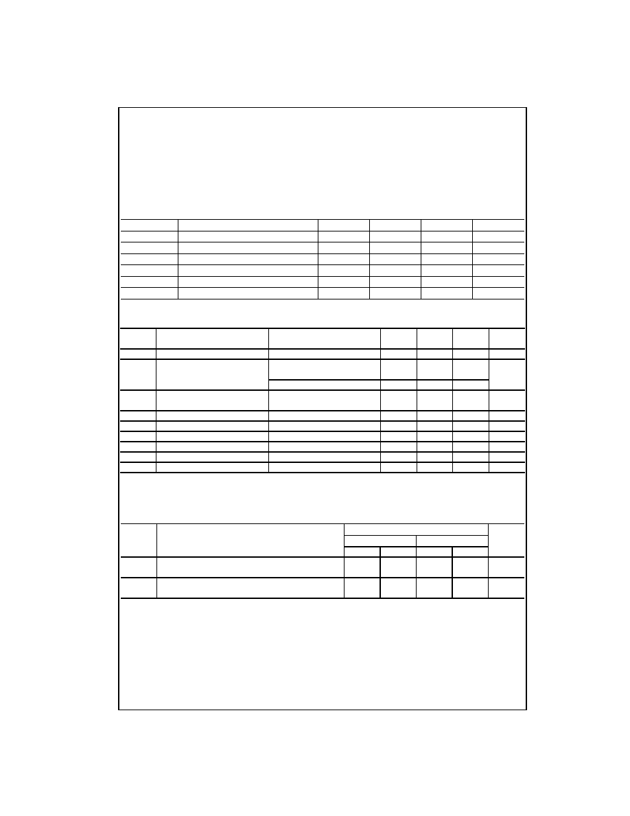
Absolute Maximum Ratings(Note 1)
Note 1: The “Absolute Maximum Ratings” are those values beyond which
the safety of the device cannot be guaranteed. The device should not be
operated at these limits. The parametric values defined in the Electrical
Characteristics tables are not guaranteed at the absolute maximum ratings.
The “Recommended Operating Conditions” table will define the conditions
for actual device operation.
Recommended Operating Conditions
Electrical Characteristics
over recommended operating free air temperature (unless otherwise noted)
Note 2: All typicals are at VCC = 5V, TA = 25°C.
Note 3: Not more than one output should be shorted at a time, and the duration should not exceed one second.
Switching Characteristics
at VCC = 5V and TA = 25°C
Supply Voltage
7V
Input Voltage
5.5V
Operating Free Air Temperature Range
0
°C to +70°C
Storage Temperature Range
65°C to +150°C
Symbol
Parameter
Min
Nom
Max
Units
VCC
Supply Voltage
4.75
5
5.25
V
VIH
HIGH Level Input Voltage
2
V
VIL
LOW Level Input Voltage
0.8
V
IOH
HIGH Level Output Current
3mA
IOL
LOW Level Output Current
60
mA
TA
Free Air Operating Temperature
0
70
°C
Symbol
Parameter
Conditions
Min
Typ
Max
Units
(Note 2)
VI
Input Clamp Voltage
VCC = Min, II = 18 mA
1.2
V
VOH
HIGH Level
VCC = Min, VIL = Max
2.7
3.4
V
Output Voltage
IOH = Max
VIL = 0.5V, RO = 50 to GND
2.0
VOL
LOW Level
VCC = Min, IOL = Max
0.5
V
Output Voltage
VIH = Min
II
Input Current @ Max Input Voltage
VCC = Max, VI = 5.5V
1
mA
IIH
HIGH Level Input Current
VCC = Max, VI = 2.7V
100
A
IIL
LOW Level Input Current
VCC = Max, VI = 0.5V
4mA
IOS
Short Circuit Output Current
VCC = Max (Note 3)
50
225
mA
ICCH
Supply Current with Outputs HIGH
VCC = Max
10
18
mA
ICCL
Supply Current with Outputs LOW
VCC = Max
25
44
mA
RL = 93
Symbol
Parameter
CL = 50 pF
CL = 150 pF
Units
Min
Max
Min
Max
tPLH
Propagation Delay Time
26.5
3
9
ns
LOW-to-HIGH Level Output
tPHL
Propagation Delay Time
26.5
3
9
ns
HIGH-to-LOW Level Output
相關(guān)PDF資料 |
PDF描述 |
|---|---|
| 74S150-C10S3 | MALE, RF CONNECTOR, PLUG |
| 75-6-11 | 0 MHz - 40000 MHz RF/MICROWAVE FIXED ATTENUATOR |
| 75-6-12 | 0 MHz - 40000 MHz RF/MICROWAVE FIXED ATTENUATOR |
| 75000H-21B-75XB | 4 CONTACT(S), METAL, MALE, MIL SERIES CONNECTOR, SOLDER, RECEPTACLE |
| 75000H-21B-75XC | 4 CONTACT(S), METAL, MALE, MIL SERIES CONNECTOR, SOLDER, RECEPTACLE |
相關(guān)代理商/技術(shù)參數(shù) |
參數(shù)描述 |
|---|---|
| 74S140DC | 制造商:Rochester Electronics LLC 功能描述:- Bulk |
| 74S140PC | 制造商:Rochester Electronics LLC 功能描述:- Bulk |
| 74S15 | 制造商:NTE Electronics 功能描述: |
| 74S151 WAF | 制造商:Texas Instruments 功能描述: |
| 74S151DC | 制造商:Rochester Electronics LLC 功能描述:- Bulk |
發(fā)布緊急采購(gòu),3分鐘左右您將得到回復(fù)。