- 您現(xiàn)在的位置:買賣IC網(wǎng) > PDF目錄360548 > 7MBP75RA-120 MCU 20LD 20 MHZ 2K EPROM with HV I/O, -40C to +125C, 20-SSOP 208mil, TUBE PDF資料下載
參數(shù)資料
| 型號(hào): | 7MBP75RA-120 |
| 英文描述: | MCU 20LD 20 MHZ 2K EPROM with HV I/O, -40C to +125C, 20-SSOP 208mil, TUBE |
| 中文描述: | IGBT的 |
| 文件頁(yè)數(shù): | 1/7頁(yè) |
| 文件大?。?/td> | 328K |
| 代理商: | 7MBP75RA-120 |
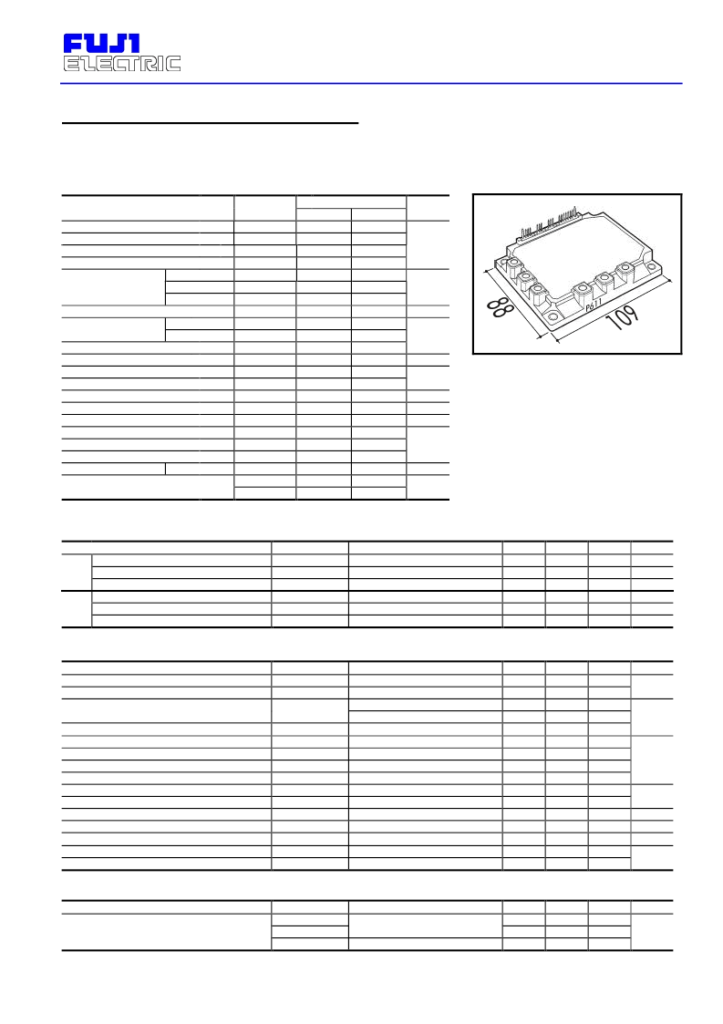
7MBP 75RA-120
IGBT IPM
1200V
6x75A+Chopper
Intelligent Power Module ( R-Series )
I
Maximum Ratings and Characteristics
Absolute Maximum Ratings
( T
c
=25°C
)
Items
Symbols
Ratings
Units
Min.
Max.
900
1000
800
1200
75
150
75
595
25
50
25
198
20
V
Z
DC Bus Voltage
DC Bus Voltage (surge)
DC Bus Voltage (short operating)
Collector-Emitter Voltage
Inverter
Collector
Current
Collector Power Dissipation
One Transistor
Dynamic Brake
Collector Current
Forward Current of Diode
Collector Power Dissi. DB
Voltage of Power Supply for Driver
Input Signal Voltage
Input Signal Current
Alarm Signal Voltage
Alarm Signal Current
Junction Temperature
Operating Temperature
Storage Temperature
Isolation Voltage
V
DC
V
DC(Surge)
V
SC
V
CES
I
C
I
CP
-I
C
P
C
I
C
I
CP
I
F
P
C
V
CC
V
IN
I
IN
V
ALM
I
ALM
T
j
T
OP
T
stg
V
iso
Mounting *1
Terminals *1
0
0
200
0
Continuous
1ms
Duty=62.6%
A
W
Continuous
1ms
A
One Transistor
W
0
0
1
mA
V
mA
0
V
CC
15
150
100
125
2500
3.5
3.5
-20
-40
°C
A.C. 1min.
V
Note:
*1:
Recommendable Value; 2.5
~
3.0 Nm (M5)
Electrical Characteristics of Power Circuit
( at T
j
=25°C, V
CC
=15V )
Items
Collector Current At Off Signal Input
INV
Collector-Emitter Saturation Voltage
Forward Voltage of FWD
Collector Current At Off Signal Input
DB
Collector-Emitter Saturation Voltage
Forward Voltage of FWD
Symbols
I
CES
V
CE(Sat)
V
F
I
CES
V
CE(Sat)
V
F
Conditions
Min.
Typ.
Max.
1.0
2.6
3.0
1.0
2.6
3.3
Units
mA
V
V
mA
V
V
V
CE
=1200V,
Input Termnal Open
I
C
=75A
-I
C
=75A
V
CE
=1200V,
Input Termnal Open
I
C
=25A
-I
C
=25A
Electrical Characteristics of Control Circuit
( at T
j
=25°C, V
CC
=15V )
Items
Current of P-Line Side Driver
(One Unit)
Current of N-Line Side Driver
(Three Units)
Symbols
I
CCP
I
CCN
Conditions
Min.
Typ.
Max.
Units
f
SW
=0~15kHz, T
C
=-20~100°C
f
SW
=0~15kHz, T
C
=-20~100°C
On
Off
R
IN
=20k
V
DC
=0V, I
C
=0A, Case Temp.
3
18
65
10
1.00
1.25
1.35
1.60
8.0
1.70
1.95
V
Input Zener Voltage
Over Heating Protection Temperature Level
Hysteresis
IGBT Chips Over Heating Protec. Temp. Level
Hysteresis
Inverter Collector Current Protection Level
DB Collector Current Protection Level
Over Current Detecting Time
Alarm Signal Hold Time
Limiting Resistor for Alarm
Under Voltage Protection Level
Hysteresis
V
Z
T
COH
T
CH
T
jOH
T
jH
I
OC
I
OC
t
DOC
t
ALM
R
ALM
V
UV
V
H
110
125
20
Surface Of IGBT Chip
150
20
T
j
=125°C
T
j
=125°C
T
j
=25°C
113
38
10
2
1500
μs
ms
1.5
1425
11.0
0.2
1575
12.5
Dynamic Characteristics
( at T
C
=T
j
=125°C, V
CC
=15V )
Items
Symbols
t
ON
t
OFF
t
RR
Conditions
Min.
0.3
Typ.
Max.
Units
I
C
=75A, V
DC
=600V
Switching Time
3.6
0.4
μs
I
F
=75A, V
DC
=600V
I
Outline Drawing
Screw Torque
V
IN(th)
Input Signal Threshold Voltage
V
V
Nm
mA
°C
A
V
相關(guān)PDF資料 |
PDF描述 |
|---|---|
| 7MBP75RE-120 | MCU CMOS 14LD 1K EPRM, 0C to +70C, 14-PDIP, TUBE |
| 7MBP75RJ-120 | MCU CMOS 14LD 1K EPRM, -40C to +125C, 14-PDIP, TUBE |
| 7MBP75RTJ-060 | MCU CMOS 14LD 1K EPRM, -40C to +85C, 14-PDIP, TUBE |
| 7MBP75TEA-060 | MCU CMOS 14LD 1K 20MHz, 0C to +70C, 14-PDIP, TUBE |
| 7MBR100U2B-060(P) | MCU CMOS 14LD 1K 20MHz, -40C to +85C, 14-SOIC 150mil, TUBE |
相關(guān)代理商/技術(shù)參數(shù) |
參數(shù)描述 |
|---|---|
| 7MBP75RA-120-55 | 制造商:Fuji Electric 功能描述:IGBT 7 PACK MOD 1200V 75A P610 |
| 7MBP75RE120 | 制造商:FUJI 制造商全稱:Fuji Electric 功能描述:IGBT-IPM |
| 7MBP75RE-120 | 制造商:未知廠家 制造商全稱:未知廠家 功能描述:7 IPM IGBT |
| 7MBP75RJ120 | 制造商:未知廠家 制造商全稱:未知廠家 功能描述:IGBT IPM R-series 1200V class 1200V / 75A 7 in one-package |
| 7MBP75RJ-120 | 制造商:未知廠家 制造商全稱:未知廠家 功能描述:IGBTs |
發(fā)布緊急采購(gòu),3分鐘左右您將得到回復(fù)。