- 您現(xiàn)在的位置:買(mǎi)賣(mài)IC網(wǎng) > PDF目錄366258 > 800Z-GF2065 3A Dual MOSFET Drvr, 0C to +70C, 16-SOIC 300mil, TUBE PDF資料下載
參數(shù)資料
| 型號(hào): | 800Z-GF2065 |
| 英文描述: | 3A Dual MOSFET Drvr, 0C to +70C, 16-SOIC 300mil, TUBE |
| 中文描述: | 輕觸式按鍵電纜康恩 |
| 文件頁(yè)數(shù): | 11/13頁(yè) |
| 文件大小: | 1995K |
| 代理商: | 800Z-GF2065 |
第1頁(yè)第2頁(yè)第3頁(yè)第4頁(yè)第5頁(yè)第6頁(yè)第7頁(yè)第8頁(yè)第9頁(yè)第10頁(yè)當(dāng)前第11頁(yè)第12頁(yè)第13頁(yè)

Bulletin 800Z
Zero-Force
Touch Buttons
Type 4/4X/13, IP66
10-342
0
Wiring Diagrams — Two-Hand Control Connections
General Purpose Line
If you use an 800
Z
5-conductor connection (i.e., 800
Z
-G
_ _ _ _
5 or 800
Z
-G
_ _ Q
5) you need to use the following Allen-Bradley/
Guardmaster
safety relay(s):
440R-D23021 (3 monitored circuits/1 auxiliary circuit) (24V AC/DC input)
440R-D23022 (3 monitored circuits/1 auxiliary circuit) (120V AC input)
440R-D23023 (3 monitored circuits/1 auxiliary circuit) (230V AC input)
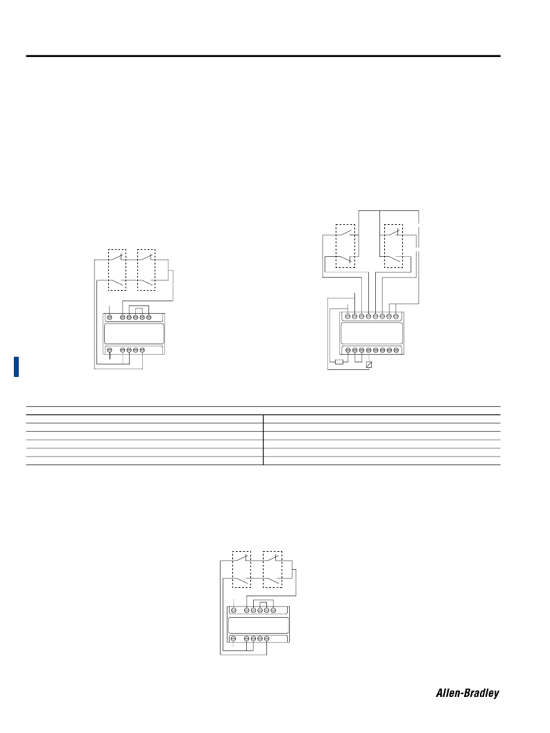
See Figure 2 below for Switch 1 (S1) and Switch 2 (S2) connections.
If you use an 800
Z
6-conductor connection (i.e., 800
Z
-G
_ _ _ _
6) you need to use the following Allen-Bradley safety relay(s):
700-
Z
BR520A
Z
1 (5 monitored circuits/2 auxiliary circuits) (24V DC/120V AC input)
440R-
Z
BR520A
Z
1 (5 monitored circuits/2 auxiliary circuits) (24V DC/120V AC input)
700-
Z
BR100A
Z
1 (1 monitored circuit) (24V DC/120V AC input)
See Figure 1 below for Switch 1 (S1) and Switch 2 (S2) connections.
Heavy Industrial Line
If you use an 800
Z
6-terminal connection (i.e., 800
Z
-HL1
_
or an 800
Z
-HF1
_
) you need to use the following Allen-Bradley safety
relay(s):
700-
Z
BR520A
Z
1 (5 monitored circuits/2 auxiliary circuits) (24V DC/120V AC input)
440R-
Z
BR520A
Z
1 (5 monitored circuits/2 auxiliary circuits) (24V DC/120V AC input)
700-
Z
BR100A
Z
1 (1 monitored circuit) (24V DC/120V AC input)
See Figure 3 below for Switch 1 (S1) and Switch 2 (S2) connections.
S1
Wire Color Codes for Bulletin 800Z General Purpose Line Touch Buttons
BROWN
BL
U
E
WHITE
BLACK
GRA
Y
PINK
L1 (+)
L2 (–)
N.C.
N.O.
N.O. common
N.C. common
S1
S2
WHITE
PINK
WHITE
BLACK
GRAY
BLACK
A1/B1
T11 T12
X1
X2
T22
A2/B2
T31 T32 T33 T34
S1
S2
GRAY
BLACK
FUSE
X1
K
1
13
14
23
24
33
34
41
42
A1 A2 S13 S14 S24 S23 X1 X2
WHITE
BLACK
WHITE
WHITE
BLACK
700-ZBR520AZ1 or 440R-ZBR520AZ1
Figure 1
440R-D23021
440R-D23022
440R-D23023
Figure 2
S2
A1/B1
T11 T12 X1 X2 T22
A2/B2
T31 T32 T33 T34
700-ZBR520AZ1 or 440R-ZBR520AZ1
Figure 3
相關(guān)PDF資料 |
PDF描述 |
|---|---|
| 800Z-GF2Q5 | SENSOR TOUCH BUTTON 5PIN CONN |
| 800Z-GL2065 | SENSOR TOUCH BUTTON CABLE CONN |
| 800Z-GL2Q5 | 3A DUAL MOSFET DRVR, -40C to +85C, 8-DFN, T/R |
| 8011B | 1.5A Dual MOSFET Drvr, 0C to +70C, 8-PDIP, TUBE |
| 80131000 | 1.5A Dual MOSFET Drvr, -40C to +85C, 8-DFN, T/R |
相關(guān)代理商/技術(shù)參數(shù) |
參數(shù)描述 |
|---|---|
| 800Z-GF2065- | 制造商:ALLEN-BRADLEY 制造商全稱:Allen-Bradley 功能描述:Zero-Force Touch Buttons |
| 800Z-GF2065B- | 制造商:ALLEN-BRADLEY 制造商全稱:Allen-Bradley 功能描述:Zero-Force Touch Buttons |
| 800Z-GF2065B-K1 | 制造商:ALLEN-BRADLEY 制造商全稱:Allen-Bradley 功能描述:Zero-Force Touch Buttons |
| 800Z-GF2065B-K2 | 制造商:ALLEN-BRADLEY 制造商全稱:Allen-Bradley 功能描述:Zero-Force Touch Buttons |
| 800Z-GF2065B-K3 | 制造商:ALLEN-BRADLEY 制造商全稱:Allen-Bradley 功能描述:Zero-Force Touch Buttons |
發(fā)布緊急采購(gòu),3分鐘左右您將得到回復(fù)。