- 您現(xiàn)在的位置:買賣IC網(wǎng) > PDF目錄209281 > 8041-1G4-1 (THOMAS BETTS CORP) INTERCONNECTION DEVICE PDF資料下載
參數(shù)資料
| 型號: | 8041-1G4-1 |
| 廠商: | THOMAS BETTS CORP |
| 元件分類: | 連接器件 |
| 英文描述: | INTERCONNECTION DEVICE |
| 文件頁數(shù): | 1/2頁 |
| 文件大?。?/td> | 23K |
| 代理商: | 8041-1G4-1 |

H
Thomas & Betts
1555 Lynnfield Road
Memphis, TN 38119
(901) 682-8221 FAX (901) 537-8805
H24
Quality & Innovation From The
Product Group
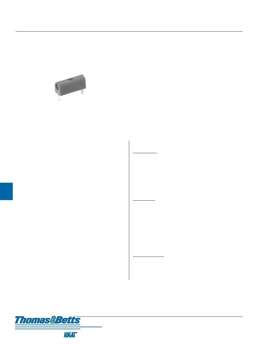
Printed Circuit Test Jacks
8041 Series
PERFORMANCE SPECIFICATIONS:
MECHANICAL
Vibration ........................ 15 G's, 0 - 55 Hz monitored for 10 micro seconds
opening per MIL-STD-202, Method 201
Mechanical Shock .......... 50 G's, monitored for 10 micro seconds opening
per MIL-STD-202, Method 202
Durability ...................... 500 Insertions
Insertion Force .............. .080 (2,03) dia. pin., 5.0 lb. max.
Withdrawal Force .......... .080 (2,03) dia. pin., 227 grams (8 oz.) min.
Permeability .................. 2.0 Mu max. MIL-I-17214
Solderability .................. Passed MIL-STD-202, Method 208
ELECTRICAL
Bulk Contact
Resistance .................. 4 Milliohms @ 5 Amps, military;
5 Milliohms @ 5 Amps, commercial
Current Rating ................ 5 Amps DC
Operating Voltage .......... 1,500 Volts RMS @ sea level,
350 Volts RMS @ 50,000 feet
Dielectric Withstanding
Voltage ...................... 2,500 Volts RMS @ sea level, 500 Volts RMS
........................................
@ 50,000 feet per MIL-STD-202, Method 301
Insulation Resistance .... 5,000 x 106 Ohms, MIL-C-39024 Section 4.6.5
Capacitance .................... 1 pF @ 5 MHZ
ENVIRONMENTAL
Operating Temperature .. -65
°C to +125°C
Salt spray ........................ 4 Milliohms @ 5 Amps per MIL-STD-202,
Method 101
Humidity ........................ 1,000 x 106 Ohms per MIL-STD-202, Method 101
Thermal Shock .............. -65
°C to +125°C per MIL-STD-202, Method 107
NOTE: Military Test Reference applies specifically to MIL-Qualified Components.
FEATURES:
The Augat 8041 Series printed wiring board mounted test jacks require
very little mounting space. Used in many applications as signal test points,
they are also used as electromechanical interfaces from daughter cards to
mother boards. Test jack M8041-15G is qualified to MIL-C-39024/11.
This series test jack accepts .080 (2,03) inch dia. test probes in either side
or top side entry models.
Low profile for close board-to-board stacking
Test jack cannot be damaged by using oversized probe
Probe side entry or top and side entry, both qualified to MIL-C-39024/11
Dimple on printed circuit terminals, retains test jack in P.W.B. during
flow soldering
Ten brilliant insulation colors available for quick test point reference
Top entry allows test jack to be probed while beingused as an intercon-
nection socket
MATERIAL SPECIFICATIONS:
Insulator ........................ Nylon
Contacts .......................... Beryllium copper
Platings .......................... Gold
8041-1G4-1
相關PDF資料 |
PDF描述 |
|---|---|
| 800-014-BCC15-85NS8C-72 | INTERCONNECTION DEVICE |
| 800-014-BCC6-4NN8C-72 | INTERCONNECTION DEVICE |
| 800-014-BCC6-4NS8B-72 | INTERCONNECTION DEVICE |
| 800-014-BCZ19-19NS2C-72 | INTERCONNECTION DEVICE |
| 800-014-BDNF9-19NS2B-72 | INTERCONNECTION DEVICE |
相關代理商/技術(shù)參數(shù) |
參數(shù)描述 |
|---|---|
| 8041-1G6 | 制造商:TE Connectivity 功能描述:8041-1G6 TEST JACK ASSY |
| 80411-NI | 制造商:Leviton Manufacturing Co 功能描述: |
| 80411-NT | 制造商:Leviton Manufacturing Co 功能描述: |
| 80411-NW | 制造商:Leviton Manufacturing Co 功能描述: |
| 8041-1SF | 制造商:Carlisle Interconnect Components 功能描述:RF COAXIAL CABLE MOUNT CONNECTOR |
發(fā)布緊急采購,3分鐘左右您將得到回復。