- 您現(xiàn)在的位置:買賣IC網(wǎng) > PDF目錄24774 > 935084920118 (NXP SEMICONDUCTORS) TELEPHONE SPEECH CKT, PDSO20 PDF資料下載
參數(shù)資料
| 型號: | 935084920118 |
| 廠商: | NXP SEMICONDUCTORS |
| 元件分類: | 無繩電話/電話 |
| 英文描述: | TELEPHONE SPEECH CKT, PDSO20 |
| 封裝: | PLASTIC, SOT-163, SO-20 |
| 文件頁數(shù): | 35/38頁 |
| 文件大?。?/td> | 303K |
| 代理商: | 935084920118 |
第1頁第2頁第3頁第4頁第5頁第6頁第7頁第8頁第9頁第10頁第11頁第12頁第13頁第14頁第15頁第16頁第17頁第18頁第19頁第20頁第21頁第22頁第23頁第24頁第25頁第26頁第27頁第28頁第29頁第30頁第31頁第32頁第33頁第34頁當前第35頁第36頁第37頁第38頁

March 1994
6
Philips Semiconductors
Product specication
Low voltage versatile telephone transmission circuit
with dialler interface and transmit level dynamic limiting
TEA1064A
FUNCTIONAL DESCRIPTION
Supplies VCC1, VCC2, LN, SLPE, REG and STAB (Fig.3)
Power for the TEA1064A and its peripheral circuits is
usually obtained from the telephone line. The IC develops
its own supply voltage at VCC1 and regulates its voltage
drop. The internal supply requires a decoupling capacitor
between VCC1 and VEE. The internal current stabilizer is
set by a 3.6 k
resistor between STAB and VEE.
The DC current flowing into the set is determined by the
exchange supply voltage Vexch, the feeding bridge
resistance Rexch, the subscriber line DC resistance Rline
and the DC voltage (including polarity guard) on the
subscriber set (see Fig.3).
The internal voltage regulator generates a
temperature-compensated reference voltage that is
available between VCC2 and SLPE
[Vref =VCC2-SLPE = 3.3 V (typ.)]. This internal voltage
regulator requires decoupling by a capacitor between REG
and VEE (C3).
The reference voltage can be used to:
regulate directly the line voltage (stabilized
VLN-SLPE =VCC2-SLPE)(1)
to stabilize the supply voltage for peripherals.
Regulated line voltage
In this application the VCC2 pin is connected to the LN pin
as shown in Fig.3. This configuration gives a stabilized
voltage across pins LN and SLPE which, applied via the
low-pass filter R16, C15, provides a supply to the
peripherals that is independent of the line current and
depends only on the peripheral supply current.
The value of R16 and the level of the DC voltage VLN-SLPE
determine the supply capabilities. In the basic application
R16 = 392
and C15 = 220 F. The worst-case
peripheral supply current as a function of supply voltage is
shown in Fig.4. To increase the supply capabilities, the DC
voltage VLN-SLPE can be increased by using RVA(REG-SLPE)
or by decreasing the value of R16.
(1) The TEA1064A application with regulated line voltage is the
same as is used for TEA1060/TEA1061, TEA1067 and
TEA1068 integrated circuits.
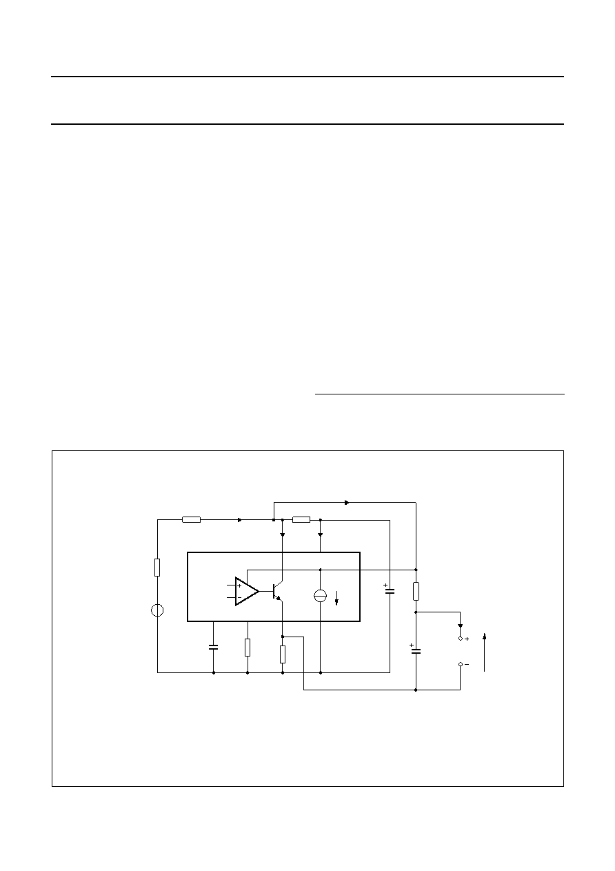
Fig.3 Application with regulated line voltage (stabilized VLN-SLPE).
The voltage VLN-SLPE is fixed to Vref = 3.3 ± 0.25 V. Resistor R16 together with the
line current determine the supply capabilities and the maximum output swing on
the line (no loop damping is necessary).
The line voltage VLN =Vref + ([Iline 1.55 mA] × R9).
handbook, full pagewidth
MGR058
Rexch
Rline
Iline
Vexch
DC
AC
17
REG
C3
R5
R9
10
STAB
20
SLPE
LN
1
VCC1
16
19 VCC2
11
VEE
0.25 mA
R1
ISLPE
ICC1
R16
C1
C15
peripheral
circuits
Vp
Ip
TEA1064A
Ip + 0.25 mA
相關(guān)PDF資料 |
PDF描述 |
|---|---|
| 935084930112 | TELEPHONE SPEECH CKT, PDIP20 |
| 0672.400 | Circular Connector; MIL SPEC:MIL-C-26482, Series I, Solder; Body Material:Aluminum; Series:PT06; Number of Contacts:55; Connector Shell Size:22; Connecting Termination:Solder; Circular Shell Style:Straight Plug; Body Style:Straight |
| 0672.500 | Circular Connector; No. of Contacts:61; Series:; Body Material:Aluminum; Connecting Termination:Solder; Connector Shell Size:24; Circular Contact Gender:Pin; Circular Shell Style:Straight Plug; Insert Arrangement:24-61 |
| 935085450112 | F/FAST SERIES, DUAL POSITIVE EDGE TRIGGERED D FLIP-FLOP, COMPLEMENTARY OUTPUT, PDSO14 |
| 935007650118 | F/FAST SERIES, DUAL POSITIVE EDGE TRIGGERED D FLIP-FLOP, COMPLEMENTARY OUTPUT, PDSO14 |
相關(guān)代理商/技術(shù)參數(shù) |
參數(shù)描述 |
|---|---|
| 935087-000 | 制造商:TE Connectivity 功能描述:301A511-51-05/164-0 - Bulk |
| 935087N001 | 制造商:TE Connectivity 功能描述:301A511-51-05/164-CS7092 制造商:TE Connectivity 功能描述:301A511-51-05/164-CS7092 - Bulk |
| 9350DC-200-0GZZZA | 制造商:Siemens 功能描述: |
| 9350DC-200-0ZZZTA | 制造商:Siemens 功能描述: |
| 9350DC-200-0ZZZZA | 制造商:Siemens 功能描述: |
發(fā)布緊急采購,3分鐘左右您將得到回復。